
Multifunctional paragliding air vehicle

An aircraft, multi-functional technology, applied in the direction of aircraft, unmanned aircraft, toy aircraft, etc., can solve the problems of increased maintenance and repair, increased aircraft weight, power loss, etc., and achieves convenient transportation, compact structure, and convenient transportation. Effect

Inactive Publication Date: 2018-08-17
王继华
View PDF0 Cites 1 Cited by
  • Summary
  • Abstract
  • Description
  • Claims
  • Application Information

AI Technical Summary

Problems solved by technology

[0003] In the design of aircraft, traditional helicopters and fixed-wing aircraft use the engine to drive the rotor screw frame to rotate through mechanical transmission. On some aircraft that use electric motors, it can also be seen that the transmission still passes through the intermediate mechanical transmission mechanism. The transmission of the intermediate transmission mechanism increases the weight of the aircraft, increases maintenance and repair, and inevitably brings additional power loss; the design of the aircraft adopts a modular design, and through the combination of different modules, a machine can be realized. Multiple types, one machine with multiple functions

Method used


Image

  • Multifunctional paragliding air vehicle
  • Multifunctional paragliding air vehicle
  • Multifunctional paragliding air vehicle

Examples


Embodiment Construction

[0029] Details and working condition of the present invention are described in detail below in conjunction with accompanying drawing:

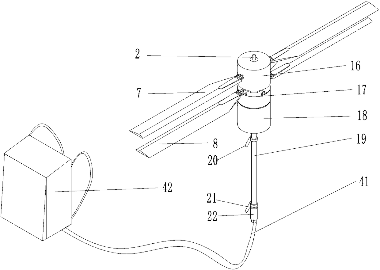
[0030] Such as figure 1 Shown is a kind of appearance schematic diagram of multifunctional paraglider aircraft of the present invention, 16 upper rotor assemblies, 17 lower rotor assemblies realize coaxial anti-propeller by 2 hollow shafts, 7 upper rotor blades, 8 lower rotor blades are respectively connected on 16 and 17 19 fuselage grip bar tops have 18 fuselage equipment compartments, 20 steering handles, 21 steering handles, and 22 control handles are installed on 19, by controlling the flight attitude of the parachute to the operation of the control handle.

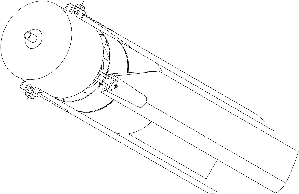
[0031] The multifunctional flying parachute aircraft of the present invention has foldable wings, like the folding of a traditional umbrella, and after folding, it is as attached figure 2 As shown, the wings are close to the fuselage, which is convenient for transportation and carr...


PUM


Abstract

The invention discloses a multifunctional paragliding air vehicle. The multifunctional paragliding air vehicle comprises a brushless hollow shaft motor, an upper rotor wing mechanism, a lower rotor wing mechanism, a reversing mechanism, a steering wheel, forward rotating rotor wing blades, reverse rotating rotor wing blades, a swashplate, a control handle and a power bagpack; wings can be folded,the wings are tightly attached to a fuselage after being folded back, and like a traditional umbrella, the structure is compact; the hollow shaft motor directly drives a lower rotor wing to rotate, anupper rotor wing and the lower rotor wing are coaxial through a hollow shaft of the motor, reversing is achieved through the gear reversing mechanism, the upper rotor wing and the lower rotor wing rotate mutually and reversely, and torque is overcome; a steering mechanism is operated, the steering wheel is attached to rotating parts of the rotor wing mechanisms, and steering of the fuselage is achieved by depending on counter-twisting force; the swashplate is operated, a head power system of the air vehicle is tilted, the rotor wings are tilted to realize flying forwards and backwards, and the direction of the air vehicle is controlled; and through the modular design, different functional modules are combined, and multi-model and multi-function of the air vehicle are achieved.

Description

technical field [0001] This patent relates to the fields of aviation, model airplanes and toy aircraft, especially the field of aviation. Background technique [0002] The development of the aviation field is changing with each passing day, and more and more aircrafts have entered the public, changing people's lives; with the development of new energy technologies, especially the development of electric The use of electric technology is increasing; in aviation vehicles, the use of electric technology will also become a positive trend. [0003] In the design of aircraft, traditional helicopters and fixed-wing aircraft use the engine to drive the rotor screw frame to rotate through mechanical transmission. On some aircraft that use electric motors, it can also be seen that the transmission still passes through the intermediate mechanical transmission mechanism. The transmission of the intermediate transmission mechanism increases the weight of the aircraft, increases maintena...

Claims


Application Information

Patent Timeline
IPC IPC(8): B64C39/02A63H27/01A63H27/133A63H27/24A63H27/20B64C31/04
CPCA63H27/02A63H27/12B64C27/007B64C31/04B64C39/02B64U50/19B64U2101/60
Inventor 王继华
Owner 王继华
Learn More