Secondary reheating system and method achieving efficient regeneration and steam exhaust optimization

A technology of secondary reheat and waste heat recovery system, applied in steam applications, steam engine installations, machines/engines, etc., can solve the problems of large volume flow, increase system complexity, low efficiency, etc., and achieve broad application prospects and make full use of effect of value

Pending Publication Date: 2018-08-17
NORTH CHINA ELECTRIC POWER UNIV (BAODING)
View PDF6 Cites 8 Cited by
  • Summary
  • Abstract
  • Description
  • Claims
  • Application Information

AI Technical Summary

Problems solved by technology

However, due to the high temperature of the main steam and the reheat steam of the double reheat unit, there is a problem that the superheated degree of the extraction steam of the regenerative heaters at all levels is very high, and the superheated extraction steam in these regenerative heaters comes from the steam turbine The pressure cylinder increases the energy loss of the double reheat unit and hinders the further improvement of the efficiency of the double reheat unit; therefore, a new system is urgently needed to solve the problem of overheating of the regenerative heater extraction steam
[0005] The traditional double reheat system increases the complexity of the system, and compared with the single reheat system, the inlet steam pressure of the low-pressure cylinder is lower and the volume flow is larger, resulting in greater energy loss. The efficiency of the low-pressure cylinder is The lowest among steam turbines, its extraction steam heats the feed water of the reheating system, which further increases the energy loss of the low-pressure cylinder, so it is necessary to optimize the overall optimization of the traditional double reheating system

Method used


Image

  • Secondary reheating system and method achieving efficient regeneration and steam exhaust optimization

Examples


Embodiment Construction

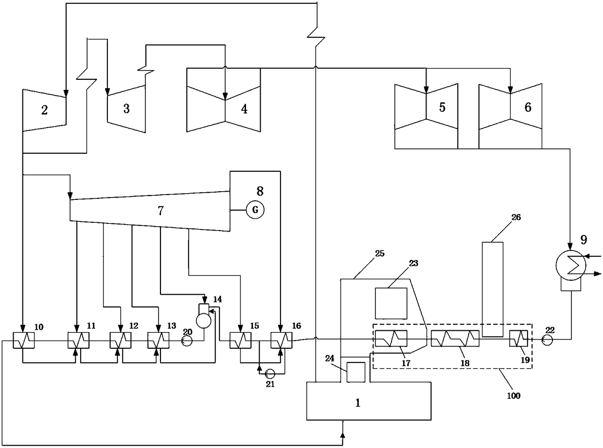
[0022] The present invention provides a high-efficiency heat recovery and optimized steam extraction secondary reheating system. The present invention will be further described in detail below in conjunction with the accompanying drawings and specific implementation methods.

[0023] Such as figure 1 As shown, the present invention provides an embodiment of a high-efficiency heat recovery and optimized steam extraction secondary reheat system, including: boiler 1, steam turbine high-pressure cylinder 2, steam turbine first-stage medium-pressure cylinder 3, steam turbine second-stage medium-pressure Cylinder 4, steam turbine first-stage low-pressure cylinder 5, steam turbine second-stage low-pressure cylinder 6, heat recovery steam turbine 7, generator 8, condenser 9, first-stage high-pressure heater 10, second-stage high-pressure heater 11, second-stage high-pressure heater Three-stage high-pressure heater 12, fourth-stage high-pressure heater 13, deaerator 14, sixth-stage low...


PUM


Abstract

The invention discloses a secondary reheating system and method achieving efficient regeneration and steam exhaust optimization, and relates to the field of thermal power generation. The system mainlycomprises a boiler, a regeneration steam turbine and a waste heat recovery system, wherein the waste heat recovery system replacing a traditional low-pressure heater is arranged between a condensatewater pump and feedwater of a seventh-stage low-pressure heater, condensate water is preliminarily heated by the waste heat recovery system through flue gas of the boiler and pipeline leaking steam ofthe regeneration steam turbine, and the waste heat recovery system is composed of a flue gas cooler, a low-temperature coal economizer and a sealing heater. The flue gas cooler, the low-temperature coal economizer and the sealing heater replace the traditional low-pressure heater to heat the feedwater, and steam exhaust energy losses of the steam turbine are reduced while heat of the boiler is recovered. The arrangement of a unit is optimized as a whole, efficient regeneration is further enhanced, and the complexity of the system is lowered. The coal consumption can be reduced by 2 g / kW.h to3 g / kW.h while the power supply efficiency of a traditional 1,000 MW secondary reheating unit is improved by 0.2% to 0.3%.

Description

[0001] Patent field [0002] The invention relates to the field of thermal power generation, in particular to a secondary reheating system and method for efficient heat recovery and optimized steam extraction. Background technique [0003] At present, large-capacity, high-parameter thermal power units have become the mainstream of thermal power units in my country. Currently, there are more than a dozen double reheat units approved or under construction. The main steam pressure is 28MPa~31MPa, and the main steam temperature is 600℃~ 620°C, higher steam parameters can improve the efficiency of the thermal power generation cycle system. Since the problem of high-temperature materials for thermal power units has not been resolved, the development projects of 700°C thermal power units in the world have encountered obstacles and will not happen in the short term. There are commercial applications, so it is necessary to continue to optimize the system from other directions to achieve ...

Claims


Application Information

Patent Timeline
Patent Type & Authority Applications(China)
IPC IPC(8): F01K17/02F01K13/00F01K21/00F01D15/10
CPCF01D15/10F01K13/00F01K17/02F01K21/00
Inventor 张思瑞李惊涛魏萌
Owner NORTH CHINA ELECTRIC POWER UNIV (BAODING)
Why Eureka
Try Eureka