Method and device capable of preventing power station boiler slagging

A utility boiler and slagging technology, applied in the field of electric power, can solve the problems of decreased heat transfer efficiency, frequent soot blowing, and furnace shutdown due to tube burst, and achieve the effects of preventing heat transfer deterioration, improving thermal economy, and preventing boiler coking.

Active Publication Date: 2019-06-07
XINAO SHUNENG TECH CO LTD
View PDF4 Cites 5 Cited by
  • Summary
  • Abstract
  • Description
  • Claims
  • Application Information

AI Technical Summary

Problems solved by technology

The operation mode of power plant boilers determines that it will inevitably produce ash pollution during operation. Due to the extremely high temperature of the internal flame, which usually exceeds the ash melting point of coal ash, the fly ash in the molten state is easy to adhere to the temperature The slag layer that is extremely difficult to remove forms on the lower water wall, which affects the heat transfer performance of the boiler. In severe cases, the temperature of the water wall may be too high, causing serious accidents such as tube burst and shutdown
[0003] Because the temperature inside the boiler is extremely high and there are problems such as fly ash erosion in the flue gas, it cannot be monitored by direct measurement. Usually, power plant boilers usually use regular and quantitative soot blowing to remove furnace slagging, but there is a lack of The problem of intuitive monitoring data will lead to soot blowing and slagging, soot blowing is not timely and the heat transfer efficiency is reduced, or soot blowing is too frequent and steam is wasted too much
As a result, a large amount of human and material resources are wasted, and a technology to prevent power plant boilers from slagging and ash accumulation is urgently needed to solve the above problems

Method used


Image

  • Method and device capable of preventing power station boiler slagging
  • Method and device capable of preventing power station boiler slagging
  • Method and device capable of preventing power station boiler slagging

Examples


Embodiment Construction

[0054] In order to make the purpose, technical solutions and advantages of the embodiments of the present invention clearer, the technical solutions in the embodiments of the present invention will be clearly and completely described below in conjunction with the drawings in the embodiments of the present invention. Obviously, the described embodiments It is a part of the embodiments of the present invention, but not all of them. Based on the embodiments of the present invention, all other embodiments obtained by those of ordinary skill in the art without creative work belong to the protection of the present invention. scope.

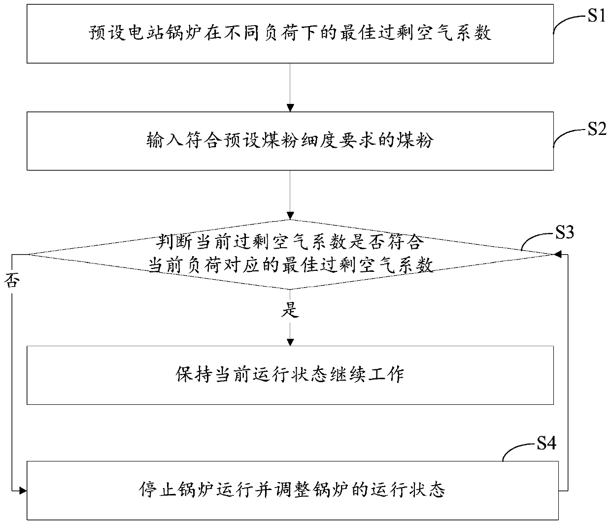
[0055] Such as figure 1 As shown, the embodiment of the present invention provides a method for preventing power plant boiler slagging, the method may include the following steps:

[0056] S1: Preset the optimal excess air coefficient of the utility boiler under different loads;

[0057] S2: Input pulverized coal that meets the preset coal fineness re...


PUM


Abstract

The invention discloses a method and device capable of preventing power station boiler slagging. The method capable of preventing power station boiler slagging comprises the steps of S1, presetting optimal excess air coefficients of a power station boiler under different loads; S2, inputting pulverized coal l meeting the preset pulverized coal fineness need; S3, judging whether the current excessair coefficient meets the optimal excess air coefficient corresponding to the current load in the power station boiler running process, if yes, continuing work with the current running state, and if not, the S4 is executed; S4, stopping boiler running, and adjusting the running state of the boiler, starting the power station boiler and executing the S3. Generation of boiler coking can be prevented, heat transfer resistance of the boiler heating face is reduced, coal consumption is reduced, the boiler heat economy is improved, meanwhile, through online analysis of the change tendency of the outlet pulverized coal finenesses of a coal grinding machine, the pulverized coal fineness is subjected to closed-loop control within the preset range, and pulverized coal fineness and uniformity stableoutput is achieved.

Description

technical field [0001] The invention relates to the technical field of electric power, in particular to a method and a device for preventing slagging of power plant boilers. Background technique [0002] Power plant boilers use coal and other fossil fuels as energy sources, and their combustion products contain a large amount of ash, sulfur and nitrogen oxides and other substances. The operation mode of power plant boilers determines that it will inevitably produce ash pollution during operation. Due to the extremely high temperature of the internal flame, which usually exceeds the ash melting point of coal ash, the fly ash in the molten state is easy to adhere to the temperature A slag layer that is extremely difficult to remove is formed on the lower water wall, which affects the heat transfer performance of the boiler. In severe cases, the temperature of the water wall may be too high, causing serious accidents such as tube burst and shutdown. [0003] Because the temper...

Claims


Application Information

Patent Timeline
Patent Type & Authority Applications(China)
IPC IPC(8): F23N5/00F23K1/00
Inventor 王小娜
Owner XINAO SHUNENG TECH CO LTD
Why Eureka
Try Eureka