Unlock instant, AI-driven research and patent intelligence for your innovation.

Flue gas condensing, dehumidifying and then heating system and method utilizing compressive heat pump

A compression type heat pump and flue gas condensation technology, applied in heat pump, separation method, combustion method and other directions, can solve the problems of white smoke from chimney, heat waste, decrease of flue gas transmittance, etc., to achieve convenient operation, simple structure, Practical effect

Pending Publication Date: 2018-08-17
HUANENG POWER INTERNATIONAL +2
View PDF5 Cites 0 Cited by
  • Summary
  • Abstract
  • Description
  • Claims
  • Application Information

AI Technical Summary

Problems solved by technology

The flue gas in the chimney is in a saturated state, the temperature is generally 40°C-55°C, the saturated flue gas discharged is rapidly cooled by the lower temperature atmosphere, the water vapor in the flue gas condenses into a liquid state, and the transmittance of the flue gas decreases, resulting in The phenomenon of white smoke from the chimney and the phenomenon of chimney rain, while the exhausted flue gas contains a large amount of condensable particulate matter such as soluble salt, sulfuric acid mist and organic matter, and causes a waste of heat

Method used


Image

  • Flue gas condensing, dehumidifying and then heating system and method utilizing compressive heat pump

Examples


Embodiment Construction

[0014] The present invention is described in further detail below in conjunction with accompanying drawing:

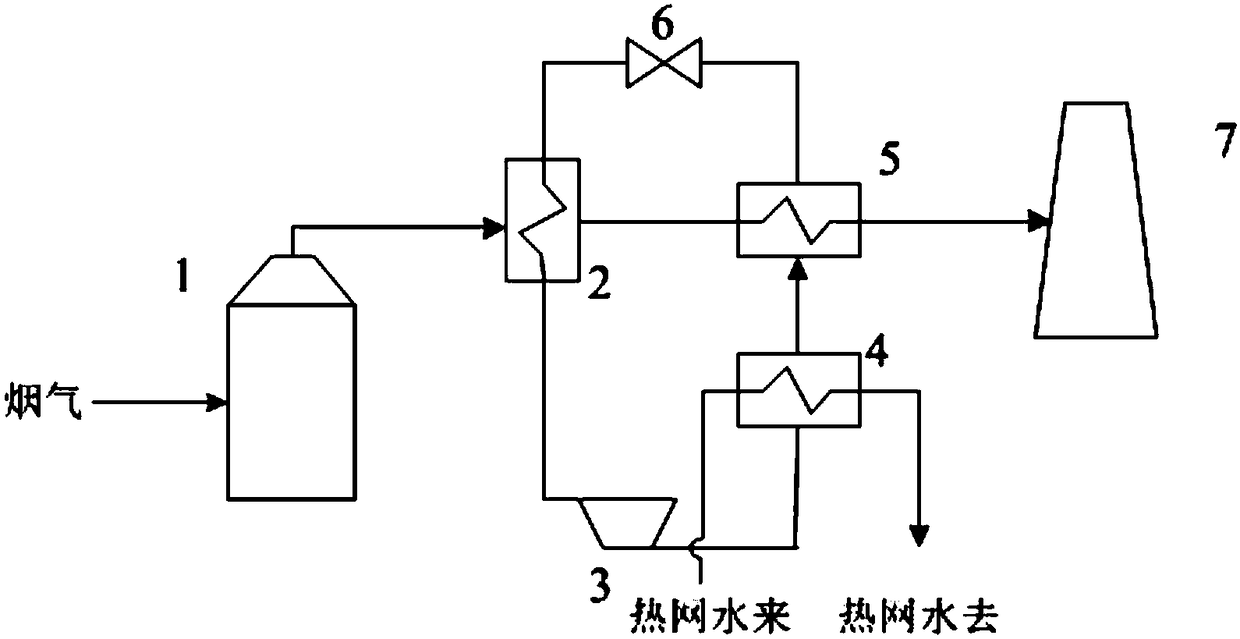
[0015] refer to figure 1 , the flue gas condensation and dehumidification reheating system using a compression heat pump according to the present invention includes a heating network water input pipeline, a heating network water output pipeline, a desulfurization absorption tower 1, a heat pump evaporator 2, a heat pump compressor 3, and a heating network water heating system 4, heat pump flue gas heater 5 and chimney 7; the outlet of desulfurization absorption tower 1 is connected with the heat release side inlet of heat pump evaporator 2, and the heat release side outlet of heat pump evaporator 2 is connected with the suction side of heat pump flue gas heater 5 The hot side inlet is connected, the heat-absorbing side outlet of the heat pump flue gas heater 5 is connected with the inlet of the chimney 7, the heat-absorbing side outlet of the heat pump evaporator 2 pas...


PUM


Abstract

The invention discloses a flue gas condensing, dehumidifying and then heating system and method utilizing a compressive heat pump. An outlet of a desulfurization absorbing tower communicates with an inlet in the heat-releasing side of a heat pump evaporator, an outlet in the heat-releasing side of the heat pump evaporator communicates with an inlet in the heat-absorption side of a heat pump flue gas heater, and an outlet in the heat-absorption side of the heat pump flue gas heater communicates with an inlet of a chimney; and an outlet in the heat-absorption side of the heat pump evaporator communicates with an inlet in the heat-releasing side of a heating network water heater through a heat pump compressor, an outlet in the heat-releasing side of the heating network water heater communicates with an inlet in the heat-releasing side of the heat pump flue gas heater, and an outlet in the heat-releasing side of the heat pump flue gas heater communicates with an inlet in the heat-absorption side of the heat pump evaporator. According to the flue gas condensing, dehumidifying and then heating system and method utilizing the compressive heat pump, heat in flue gas output from the desulfurization absorbing tower can be recovered, meanwhile, the quantity of condensable particulate matter in the flue gas discharged from the chimney can be decreased, and the phenomenon that white smoke is discharged from the chimney and the chimney rain phenomenon are avoided.

Description

technical field [0001] The invention belongs to the field of energy conservation and environmental protection, and relates to a flue gas condensation dehumidification reheating system and method, in particular to a flue gas condensation dehumidification reheating system and method using a compression heat pump. Background technique [0002] In the field of flue gas desulfurization, more than 90% of them currently adopt the wet flue gas desulfurization process, and the saturated wet flue gas after desulfurization is discharged through the wet chimney. The flue gas in the chimney is in a saturated state, the temperature is generally 40°C-55°C, the saturated flue gas discharged is rapidly cooled by the lower temperature atmosphere, the water vapor in the flue gas condenses into a liquid state, and the transmittance of the flue gas decreases, resulting in The phenomenon of white smoke from the chimney and the phenomenon of chimney rain, while the exhausted flue gas contains a la...

Claims


Application Information

Patent Timeline
IPC IPC(8): F25B30/06F24H4/02F23J15/02F23J15/06F23J15/08B01D53/00
CPCB01D53/002F23J15/02F23J15/06F23J15/08F24H4/02F25B30/06F23J2215/20B01D2258/0283
Inventor 牛拥军徐晓光张华东申建汛萧云志陈景硕雷鸣李兴华李振生宦宣州李楠
Owner HUANENG POWER INTERNATIONAL
Features
  • R&D
  • Intellectual Property
  • Life Sciences
  • Materials
  • Tech Scout
  • Unparalleled Data Quality
  • Higher Quality Content
  • 60% Fewer Hallucinations
Learn More