
Method and module for detecting gas in excimer laser discharge chamber

An excimer laser and detection module technology, applied in instruments, measuring devices, scientific instruments, etc., can solve problems such as inability to connect equipment to a discharge cavity, high laser operating pressure, equipment damage, etc., to improve efficiency and operating effects, reduce Time and energy wastage, the effect of improving efficiency and effectiveness

Pending Publication Date: 2018-08-17
ACAD OF OPTO ELECTRONICS CHINESE ACAD OF SCI
View PDF0 Cites 2 Cited by
  • Summary
  • Abstract
  • Description
  • Claims
  • Application Information

AI Technical Summary

Problems solved by technology

At the same time, because the halogen medium is extremely corrosive, and the operating pressure of the laser is much higher than the atmospheric pressure, it is not possible to directly connect the various devices used in the above research to the discharge chamber, otherwise the equipment will be damaged, and the halogen medium will also React with substances in the gas channel to generate unnecessary impurities, which will affect the detection results

Method used


Image

  • Method and module for detecting gas in excimer laser discharge chamber
  • Method and module for detecting gas in excimer laser discharge chamber
  • Method and module for detecting gas in excimer laser discharge chamber

Examples


Embodiment 1

[0061] Taking the ArF excimer laser as an example, the discharge cavity mainly includes typical copper alloy electrodes, aluminum alloy cavity walls and impellers, and alumina ceramic auxiliary parts.

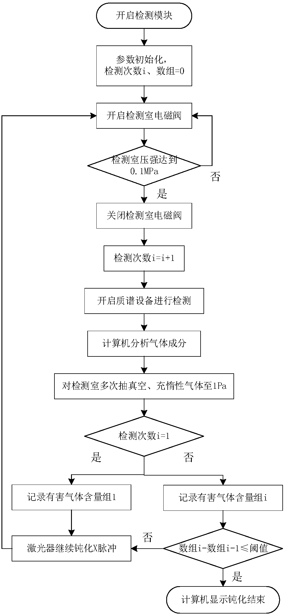
[0062] The gas in the passivation process of the discharge cavity of the excimer laser of the present invention is used to detect the gas in the passivation of the discharge cavity of the ArF excimer laser, and the results are as follows:

[0063] The following table (table 1) shows the gas content value (in ppm, ie 10 -6 ).

[0064]

O 2 content

CO 2 content

HF content

SiF 4 content

CF 4 content

N 2 content

i=1

0.5

0.7

12.4

5.4

10.8

i=2

0.7

0.9

16.9

9.4

14.2

0.2

i=n-2

1.1

1.4

23.3

18.2

18.6

0.4

i=n-1

1.2

1.4

25.9

19.6

19.9

0.4

i=n

1.2

1.5

26.4

20.4

21.2

0.5

[0065] Among them, D.L. refers to the detection limit of the device, and n is the number of detections at the end of the detection.

[0066] In this embodiment O 2 , CO 2 , HF, SiF 4 The gas difference threshold is ...

Embodiment 2

[0068] Taking the ArF excimer laser as an example, the discharge cavity mainly includes typical copper alloy electrodes, aluminum alloy cavity walls and impellers, and alumina ceramic auxiliary parts.

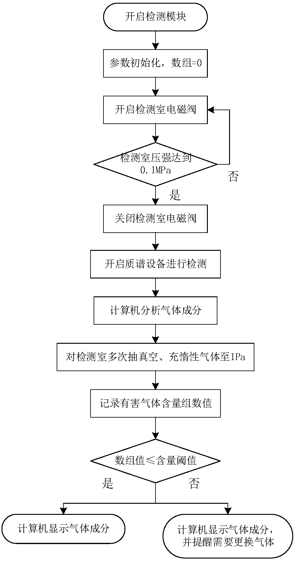
[0069] Using the method for detecting discharge cavity gas before / during the operation of the excimer laser of the present invention, the gas in the discharge cavity before / during the operation of the ArF excimer laser is detected, and the results are as follows:

[0070] The following table (table 2) shows the gas content value (in ppm, ie 10 -6 ).

[0071]

O 2 content

CO 2 content

HF content

SiF 4 content

CF 4 content

N 2 content

i=1

0.6

7.0

0.3

i=2

3.5

0.8

10.2

3.8

2.1

i=n-2

11.1

0.7

16.2

8.3

7.8

0.2

i=n-1

12.3

0.7

19.8

9.4

9.4

0.2

i=n

12.7

0.8

21.4

10.1

9.7

0.4

[0072] Among them, D.L. refers to the detection limit of the device, and n is the number of detections at the end of the detection.

[0073] In this embodiment O 2 , CO 2 , HF, SiF 4 ...


PUM


Abstract

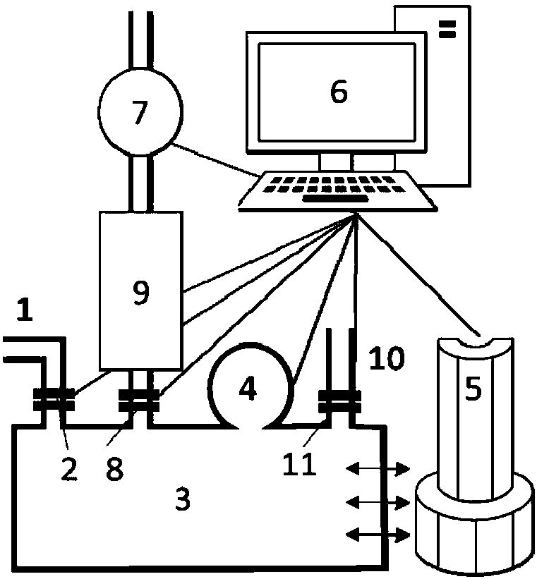
The invention relates to a method and module for detecting a gas in an excimer laser discharge chamber. The detection module comprises a gas inlet tube, a gas inlet solenoid valve, a gas chamber, a pressure detector, a mass spectrometer, a computer, a vacuum pump, a vacuum pipeline solenoid valve, a halogen gas processor, an inert gas pipeline and an inert gas solenoid valve. The detection of thegas in the excimer laser discharge chamber in the passivation process or the passivation / operation process is realized by the detection module. T The detection method and the module reduce unnecessarytime and energy wastes in the passivation / operation process, and improve the passivation efficiency and the operation effect.

Description

Technical field [0001] The invention relates to an excimer laser, in particular to a method and module for detecting gas in a discharge cavity of the excimer laser. Background technique [0002] Excimer laser is an important laser device in the ultraviolet band. It relies on the transition of molecules formed by excited mixed gas to the ground state to produce laser. The mixed gas is generally composed of inert gas and halogen gas, such as argon (Ar) and fluorine (F). 2 ), krypton (Kr) and fluorine, xenon (Xe) and chlorine (Cl 2 )Wait. Halogen media such as fluorine and chlorine are extremely corrosive to most materials, which can cause corrosion of parts in the discharge chamber during use, and react with Si, C, H, O and other elements to generate harmful gaseous products. Studies have shown that HF ​​and O in the order of 10ppm 2 , CF 4 Such harmful gases significantly affect the output power of the laser. Therefore, the lowest possible harmful gas content is an important prer...

Claims


Application Information

Patent Timeline
IPC IPC(8): G01N27/64
CPCG01N27/64
Inventor 郭馨丁金滨周翊王宇张立佳刘斌崔惠绒
Owner ACAD OF OPTO ELECTRONICS CHINESE ACAD OF SCI
Learn More