DC limiter and synergic control method of same and DC circuit breaker

A DC circuit breaker and current limiter technology, applied in the field of power transmission and distribution, can solve the problems of shortened equipment life, slow speed, and long fault current cut-off time, and achieve the effects of shortening cut-off time, reducing costs and prolonging life

Inactive Publication Date: 2018-08-17
GLOBAL ENERGY INTERCONNECTION RES INST CO LTD +3
View PDF5 Cites 7 Cited by
  • Summary
  • Abstract
  • Description
  • Claims
  • Application Information

AI Technical Summary

Problems solved by technology

However, the existing technology only stays at the level of independent control of the DC current limiter and the DC circuit breaker. When the DC circuit breaker cuts off the fault current, if the current limiting inductance in the DC current limiter still exists in the current path, it will inhibit The attenuation of the fault current, the cut-off time of the fault current is longer, the speed is slower, and the large current exceeds the current stress that the equipment in the HVDC transmission system can withstand, shortening the life of the equipment

Method used


Image

  • DC limiter and synergic control method of same and DC circuit breaker
  • DC limiter and synergic control method of same and DC circuit breaker
  • DC limiter and synergic control method of same and DC circuit breaker

Examples


Embodiment 1

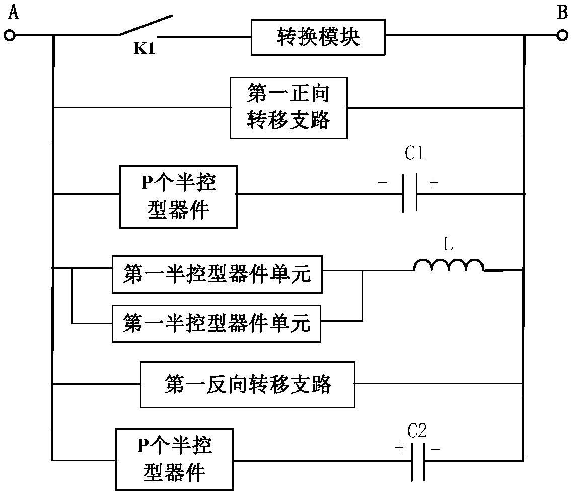
[0054] Embodiment 1 of the present invention provides a DC current limiter, the specific structure is as follows figure 1 As shown, K1 represents the fast mechanical switch in the DC current limiter, including the first flow branch, the first transfer branch and the current limiting branch. The functions of these three branches are described in detail below:

[0055] The first current-through branch is used to realize the conduction of the steady-state current of the DC line when the DC line is in normal operation, and transfer the fault current to the first transfer branch after detecting a fault in the DC line;

[0056] The first transfer branch is used to transfer the fault current on the first current flow branch to the current limiting branch;

[0057] The current limiting branch is used to carry the fault current transferred by the first current passing branch, and connect the current limiting inductor in the current limiting branch to the DC line.

[0058] 1. The first...

Embodiment 2

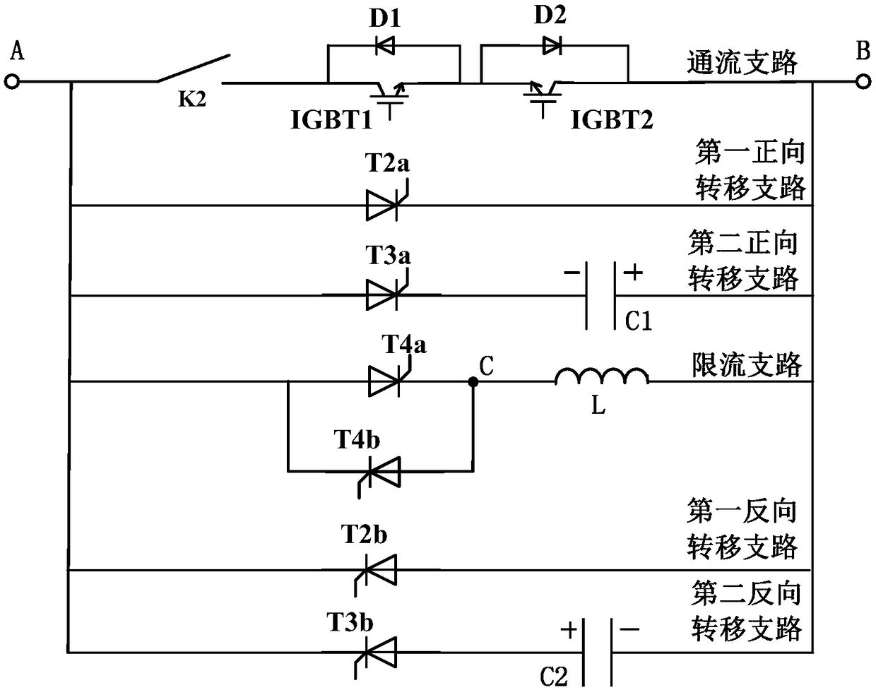
[0080] Embodiment 2 of the present invention provides a DC current limiter, the specific structure is as follows figure 2 As shown, K2 represents the fast mechanical switch in the DC current limiter. The DC current limiter provided by Embodiment 2 of the present invention includes a first flow branch, a first transfer branch and a current limiting branch. The following three The function of the branch is described in detail:

[0081] The first current-through branch is used to realize the conduction of the steady-state current of the DC line when the DC line is in normal operation, and transfer the fault current to the first transfer branch after detecting a fault in the DC line;

[0082] The first transfer branch is used to transfer the fault current on the first current flow branch to the current limiting branch;

[0083] The current limiting branch is used to carry the fault current transferred by the first current passing branch, and connect the current limiting inductor...

Embodiment 3

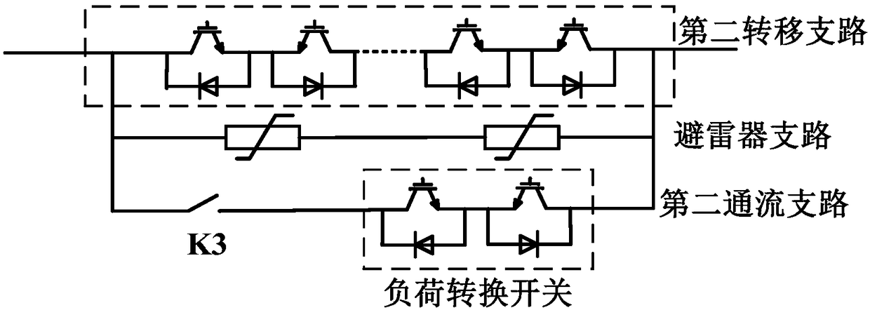
[0103] Embodiment 3 of the present invention provides a coordinated control method for the DC current limiter and the DC circuit breaker in Embodiment 1, wherein the DC circuit breaker includes a second current flow branch, a second transfer branch and a lightning arrester branch connected in parallel, The specific structure is as image 3 As shown, K3 is a fast mechanical switch in the DC circuit breaker; the flow chart of the coordinated control method for the DC current limiter and the DC circuit breaker provided by Embodiment 3 of the present invention is as follows Figure 4 As shown, the specific process includes:

[0104]S101: When the current direction is forward and the high-voltage DC power transmission system where the DC current limiter is located is operating normally (normal mode), turn on all the IGBTs in the first current flow branch and the second current flow branch, and the current flows through the first current flow branch. The first flow branch and the s...


PUM


Abstract

The invention provides a DC limiter and a synergic control method of the same and a DC circuit breaker. The DC limiter comprises a first current through branch, a first transferring branch and a current limiting branch. By the DC limiter, a fault current can be prevented from being raised, and time is provided for fault detection; and moreover, a large amount of half-control devices are employed,and the cost of the DC limiter is reduced. According to the synergic control method of the DC limiter and the DC circuit breaker, provided by the invention, a positive current direction and a negativecurrent direction are performed, synergic control of the DC limier and the DC circuit breaker is achieved by controlling on/off of the half-control devices, the advantages of the DC limiter and the circuit breaker are fully developed, meanwhile, the influence of a DC circuit inductor on current cutting speed is prevented, the fault current cutoff time is reduced, the lifetime of equipment in a high-voltage DC power transmission system is prolonged, the fault misjudgment probability can be reduced, and the reliability of the high-voltage DC power transmission system is improved.

Description

technical field [0001] The invention relates to the technical field of power transmission and distribution, in particular to a DC current limiter and a coordinated control method with a DC circuit breaker. Background technique [0002] Flexible DC transmission based on Modular Multilevel Converter (MMC) has the advantages of high modularity, flexible control of active and reactive power, and the ability to supply power to passive loads. It is widely used in wind farm grid connection, island and Weak grid power supply and urban power supply and other fields. The multi-terminal DC grid technology based on flexible DC transmission can well solve the problems of "abandoning wind" and "abandoning light" caused by new energy grid integration and consumption. Therefore, the multi-terminal flexible DC grid will play a greater role in the future power system. [0003] At present, DC current limiters and DC circuit breakers have become research hotspots, and many schemes have been u...

Claims


Application Information

Patent Timeline
Patent Type & Authority Applications(China)
IPC IPC(8): H02H7/26H02H9/02H02H3/087
CPCH02H3/087H02H7/268H02H9/02
Inventor 赵成勇邱宇峰吴亚楠杨杰王晓宇许建中韩乃峥
Owner GLOBAL ENERGY INTERCONNECTION RES INST CO LTD
Why Eureka
Try Eureka