
High-power-density motor

A high power density, collector ring technology, applied in synchronous motors with stationary armatures and rotating magnets, electromechanical devices, electrical components, etc. Problems such as poor heat dissipation capacity of the motor, to achieve the effect of improving heat dissipation capacity, reducing contact resistance, and high torque density

Pending Publication Date: 2018-08-17
五羊—本田摩托(广州)有限公司
View PDF0 Cites 1 Cited by
  • Summary
  • Abstract
  • Description
  • Claims
  • Application Information

AI Technical Summary

Problems solved by technology

In a certain slot space, it is difficult to wind as many wires as possible and as thick as possible. In this way, the volume of the motor needs to be increased slightly to increase the slot area of ​​the motor, and the degree of power density increase is also affected.
In addition, the smaller the volume of the motor and the higher the slot fullness rate, the worse the heat dissipation capability of the motor, resulting in an increase in the steady-state temperature of the motor and a decrease in the output peak power

Method used


Image

  • High-power-density motor
  • High-power-density motor
  • High-power-density motor

Examples


Embodiment Construction

[0036] The preferred embodiments of the present invention will be described below in conjunction with the accompanying drawings. It should be understood that the preferred embodiments described here are only used to illustrate and explain the present invention, and are not intended to limit the present invention.

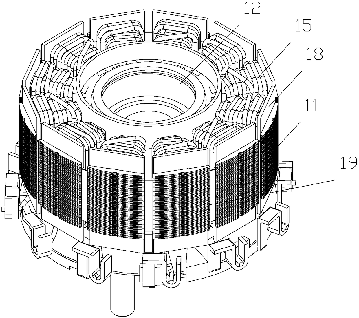
[0037] The invention discloses a permanent magnet synchronous motor structure with high power density, which includes a stator assembly 1 and a rotor 2 . The stator assembly 1 includes a stator core 11, an insulating frame 18, a stator winding 15 wound on the stator core and the insulating frame, a stator bushing 12, an end collector ring 14 and an end insulating plate 13 made of insulating material. The stator core 11 is wound with an enameled wire to form a stator coil, and the coils on two adjacent teeth form a group of stator windings 15, and two taps are respectively drawn from the two ends of each group of windings.

[0038] Such as Figure 7 The stator bushi...


PUM


Abstract

The invention provides a high-power-density motor, which comprises a stator assembly and an outer rotor, wherein the stator assembly comprises a stator iron core, an insulation framework, a stator winding, a stator bushing, an end collector ring and an end insulating plate. The stator bushing is provided with an axial inner hole for installing and connecting a motor rotating shaft, the stator ironcore and the end insulating plate are respectively provided with an inner hole and respectively sleeve outside the upper and lower sections of the stator bushing. The end collector ring is arranged on the surface of the end insulating plate and has an axial clearance from the stator iron core. A binding post is arranged on one surface, away from the stator iron core, of the end collector ring. Aheat conductor formed by pouring high heat conduction materials is arranged outside a stator slot enameled wire and a slot insulation component, the axial clearance space between the end insulating plate and the stator iron core and the outer surface of the assembled stator iron core, an insulating framework, the stator winding, the end collector ring and the enameled wire, and the binding post extends out of the surface of the heat conductor. According to the invention, the heat dissipation capacity of the motor and the output torque capacity of the motor at a certain rotating speed are improved.

Description

technical field [0001] The invention belongs to the technical field of electric motorcycle driving motors, and in particular relates to a high power density permanent magnet synchronous motor structure. Background technique [0002] High-speed permanent magnet synchronous motors are widely used in electric and hybrid vehicles because of their good performance and high efficiency. At present, more and more electric motorcycles also use high-speed permanent magnet synchronous motors as their power source. Due to the limited installation space of the motorcycle power system, the permanent magnet synchronous motor is required to have a high power density. To increase the power density of the motor, there are two main ways: to increase the output power of the motor (electric load and magnetic load), and to reduce the volume and mass of the motor. [0003] However, increasing the output power of the motor and reducing the size of the motor are contradictory. In order to reduce ...

Claims


Application Information

Patent Timeline
IPC IPC(8): H02K21/22H02K1/14H02K3/34H02K3/38H02K1/27
CPCH02K1/14H02K1/2786H02K3/345H02K3/38H02K21/22
Inventor 方建平施继民李一东
Owner 五羊—本田摩托(广州)有限公司
Learn More