Eureka AIR delivers breakthrough ideas for toughest innovation challenges, trusted by R&D personnel around the world.

Automatic feeding device for processing step drill

A technology of automatic feeding and step drilling, applied in metal processing, metal processing equipment, manufacturing tools, etc., can solve the problems of easy error, waste of raw materials, time-consuming and labor-intensive, etc., to achieve accurate processing, reduce labor intensity, and improve work efficiency Effect

Pending Publication Date: 2018-08-21
ZHENGJIANG DANTU DISTRICT NINGBO RUN TOOLS
View PDF0 Cites 0 Cited by
  • Summary
  • Abstract
  • Description
  • Claims
  • Application Information

AI Technical Summary

Problems solved by technology

[0002] Step drill, also known as step drill or pagoda drill, is mainly used for drilling thin steel plates within 3mm. One drill bit can replace multiple drill bits. Holes with different diameters can be processed according to needs, and large holes can be processed at one time. There is no need to replace drill bits and make positioning holes, etc. Some of the existing step drilling processing equipment uses manual loading and unloading, which is time-consuming and laborious, and is prone to errors. If there is an error, there will be more feed or less feed, so that there will be a large error in the processed step drill, and it is easier to waste raw materials

Method used


Image

  • Automatic feeding device for processing step drill
  • Automatic feeding device for processing step drill
  • Automatic feeding device for processing step drill

Examples


Embodiment Construction

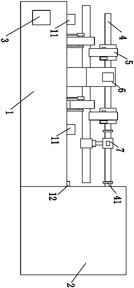
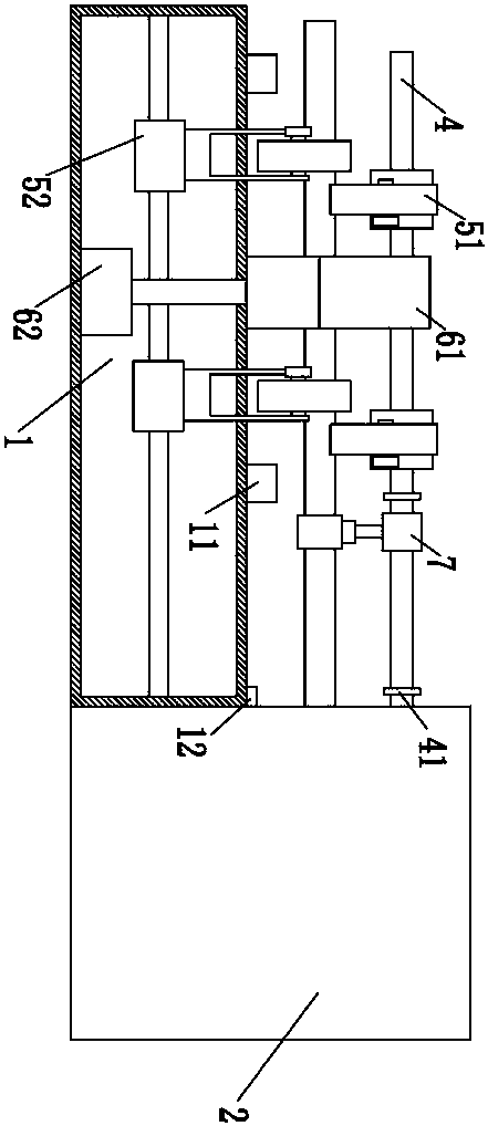
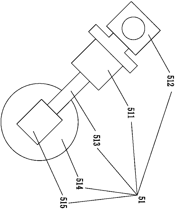
[0022] Such as Figure 1-5 As shown, an automatic feeding device for processing step drills, including a workbench 1, a processing device 2 is provided on the right side of the workbench 1, and a PLC controller for controlling the entire automatic feeding device is provided on the workbench 1 3. The PLC controller 3 is set near the left end of the workbench 1, the support shaft 4 is arranged obliquely above the workbench 1, the support frame 11 for placing raw materials is arranged on the workbench 1, and a The support frame 11 is fixedly installed on one side of the workbench 1, and the other support frame 11 is fixedly installed on the other side of the workbench 1. The automatic feeding device also includes a rotation mechanism 5, a limit mechanism 6 and a propulsion mechanism 7. The rotation There are two groups of mechanisms 5, each group of rotating mechanisms 5 includes an upper rotating mechanism 51 and a lower rotating mechanism 52, the upper rotating mechanism 51 and...


PUM


Abstract

The invention discloses an automatic feeding device for processing a step drill. The automatic feeding device comprises a working table, a PLC (Programmable Logic Controller), a support shaft, a rotating mechanism, a limiting mechanism and a thrusting mechanism, wherein the rotating mechanism is used for rotating a raw material rod; the limiting mechanism comprises an upper limiting mechanism anda lower limiting mechanism; the upper limiting mechanism comprises an upper limiting mechanism and a lower limiting mechanism; the lower limiting mechanism comprises a lifting motor, a lifting rod anda second limiting block. The raw material rod is limited by the first limiting block and the second limiting block, and then the raw material rod can be prevented from sliding off when being rotated;the thrusting mechanism comprises a sliding sleeve, a linear lifting motor, a grasping motor and grasping claws; the raw material rod is tightly grasped by the grasping claws and is moved through thethrusting sliding sleeve, and then a good moving effect can be achieved; an infrared sensor is arranged at the tail end of the right side of the working table; when being moved right above the infrared sensor, the raw material rod can be sensed in time, a feeding distance can be calculated, and the processing precision can be improved; by adopting the automatic feeding device, the raw material rod can be intelligently conveyed into a processing device, and time and labor can be saved.

Description

technical field [0001] The invention relates to the technical field of feeding devices, in particular to an automatic feeding device for step drilling. Background technique [0002] Step drill, also known as step drill or pagoda drill, is mainly used for drilling thin steel plates within 3mm. One drill bit can replace multiple drill bits. Holes with different diameters can be processed according to needs, and large holes can be processed at one time. There is no need to replace drill bits and make positioning holes, etc. Some of the existing step drilling processing equipment uses manual loading and unloading, which is time-consuming and laborious, and is prone to errors. If there is an error, there will be more feed or less feed, so that there will be a large error in the processed step drill, and it is easier to waste raw materials. Contents of the invention [0003] The purpose of the present invention is to provide an automatic feeding device for step drilling, which ...

Claims


Application Information

Patent Timeline
IPC IPC(8): B23B47/00B23Q7/04
CPCB23B47/00B23Q7/04Y02P70/10
Inventor 徐启祥
Owner ZHENGJIANG DANTU DISTRICT NINGBO RUN TOOLS
Why Eureka
Eureka Blog
Learn More