A laser marking device

A technology of laser coding and equipment, applied in the field of laser coding, can solve the problems of low coding efficiency, cumbersome coding process, error-prone, etc., and achieve the effect of meeting coding requirements

Active Publication Date: 2020-04-24
ZHANGJIAGANG KANGDE XIN OPTRONICS MATERIAL
View PDF6 Cites 0 Cited by
  • Summary
  • Abstract
  • Description
  • Claims
  • Application Information

AI Technical Summary

Problems solved by technology

However, since the same 3D plate often includes a variety of sealing frames with different widths, multiple lasers are required to generate laser beams with different line widths when coding, and a laser beam with a line width is used to complete the corresponding one on the 3D plate. Therefore, it is necessary to use multiple lasers to code multiple times to complete the stripping of the ITO material on the entire 3D flat panel. The coding process is cumbersome, the coding efficiency is low, and error-prone

Method used


Image

  • A laser marking device
  • A laser marking device
  • A laser marking device

Examples


Embodiment Construction

[0044] The present invention will be further described in detail below in conjunction with the accompanying drawings and embodiments. It should be understood that the specific embodiments described herein are only used to explain the present invention, but not to limit the present invention. In addition, it should be noted that, for the convenience of description, the drawings only show some but not all structures related to the present invention.

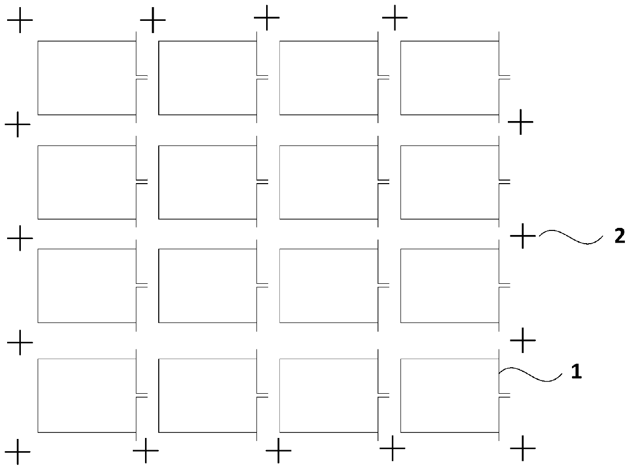
[0045] figure 1 It is a schematic structural diagram of a coding drawing provided by an embodiment of the present invention. The coding drawing includes two coding lines with different line widths. When coding the ITO glass on the flat plate according to the coding drawing, the coding lines with different line widths on the coding drawing correspond to the different widths on the ITO glass. Seal box. Among them, the coding line 1 corresponds to the standard frame on the ITO glass, and the coding line 2 corresponds to the general...


PUM

PropertyMeasurementUnit
widthaaaaaaaaaa
widthaaaaaaaaaa

Abstract

The embodiment of invention discloses laser marking equipment. The laser marking equipment comprises a laser source, a light path adjusting module and multiple light beam adjusting devices. The lasersource is used for generating laser beams. The multiple light beam adjusting devices are used for adjusting the laser beams to different line widths. The light path adjusting module is used for determining the pre-marking laser line width according to a marking drawing and adjusting the transmission direction of the laser beams generated by the laser source according to the pre-marking laser linewidth, so that the laser beams are emitted into the corresponding light beam adjusting devices. By arranging the multiple light beam adjusting devices, the light path adjusting module is utilized forcontrolling the spreading direction of the laser beams generated from the laser source, the laser beams can be emitted into different light beam adjusting devices according to needs, the line widths of the laser beams are adjusted through the light beam adjusting devices, and the marking work of different line widths is completed through one laser source.

Description

technical field [0001] Embodiments of the present invention relate to the technical field of laser coding, and in particular, to a laser coding device. Background technique [0002] In the process of preparing the naked-eye 3D flat panel, it is usually necessary to grow a layer of indium tin oxide (Indium Tin Oxides, ITO) material on the substrate of the 3D flat panel, and form a sealing frame on the side of the ITO material away from the substrate. Since the sealing frame will bring in a certain amount of water vapor during the formation process, when the 3D flat panel display works, the current flowing in the ITO material will electrochemically react with the water vapor in the sealing frame, thereby corroding the 3D flat panel. In order to prevent the corrosion of the 3D plate due to electrochemical reaction, it is necessary to peel off the ITO material corresponding to the position of the sealing frame. [0003] In the prior art, laser coding is often used to peel off t...

Claims


Application Information

Patent Timeline
Patent Type & Authority Patents(China)
IPC IPC(8): B23K26/00B23K26/064B23K26/70
CPCB23K26/00B23K26/0648B23K26/702
Inventor 王艳军
Owner ZHANGJIAGANG KANGDE XIN OPTRONICS MATERIAL
Why Eureka
Try Eureka