
Hydraulic booster pump

A booster pump and hydraulic technology, which is applied in the field of hydraulic booster pumps, can solve problems such as inconvenient portability, large volume and weight, and complex structure.

Active Publication Date: 2018-08-21
平湖必益清洁设备有限公司
View PDF6 Cites 5 Cited by
  • Summary
  • Abstract
  • Description
  • Claims
  • Application Information

AI Technical Summary

Problems solved by technology

At present, the traditional hydraulic booster pump used in China controls the reciprocating motion of the booster pump to continuously output high pressure through the continuous reversing of the electromagnetic reversing valve. The structure is complex, and complex displacement sensors and electronic control components need to be installed. Inconvenient to carry, difficult to use in flammable and explosive occasions and portable machinery, such as natural gas compression sub-stations, garbage compression stations, oil mines, coal injection, etc. have explosion-proof requirements, and the objective requirement is that the hydraulic booster pump can meet the needs of personnel without close distance Intervention can change direction by itself and also meet the requirements of explosion protection

Method used


Image

  • Hydraulic booster pump
  • Hydraulic booster pump
  • Hydraulic booster pump

Examples


Embodiment Construction

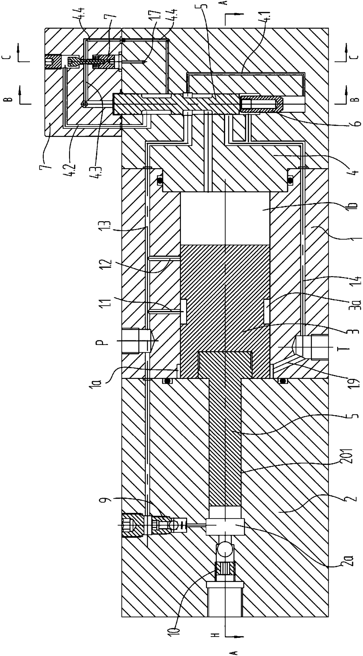
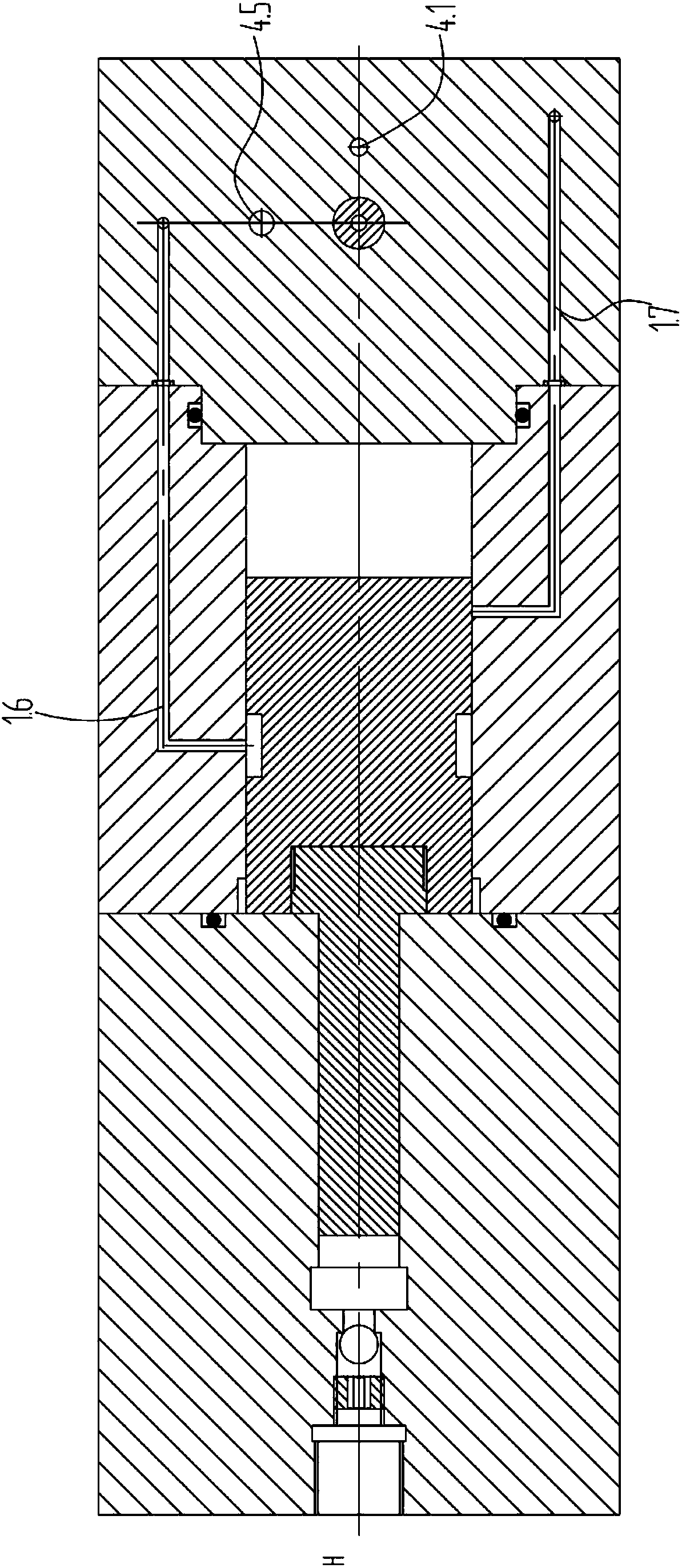
[0024] see Figure 1-4 , the present invention provides a hydraulic booster pump, comprising a cylinder 1 with a piston 3 slidably connected inside, a left end cover 2 is installed on the left end of the cylinder 1, and a right end cover 4 is installed on the right end of the cylinder 1; The left end cover 2 is horizontally provided with a jack 201 communicating with the cylinder, and the jack 201 is slidably connected with a plunger 5 connected to the piston 3; the left end of the piston 3 is connected to the piston 3 A left piston control cavity 1a is formed between the left end cover 2, a right piston control cavity 1b is formed between the right end of the piston 3 and the right end cover 4, and a right piston control cavity 1b is formed between the left end of the insertion hole 201 and the left end of the plunger 5. forming a high pressure chamber 2a;

[0025]The right end cover 4 is provided with a valve hole 401 along the vertical direction, and the first oil port 4a,...


PUM


Abstract

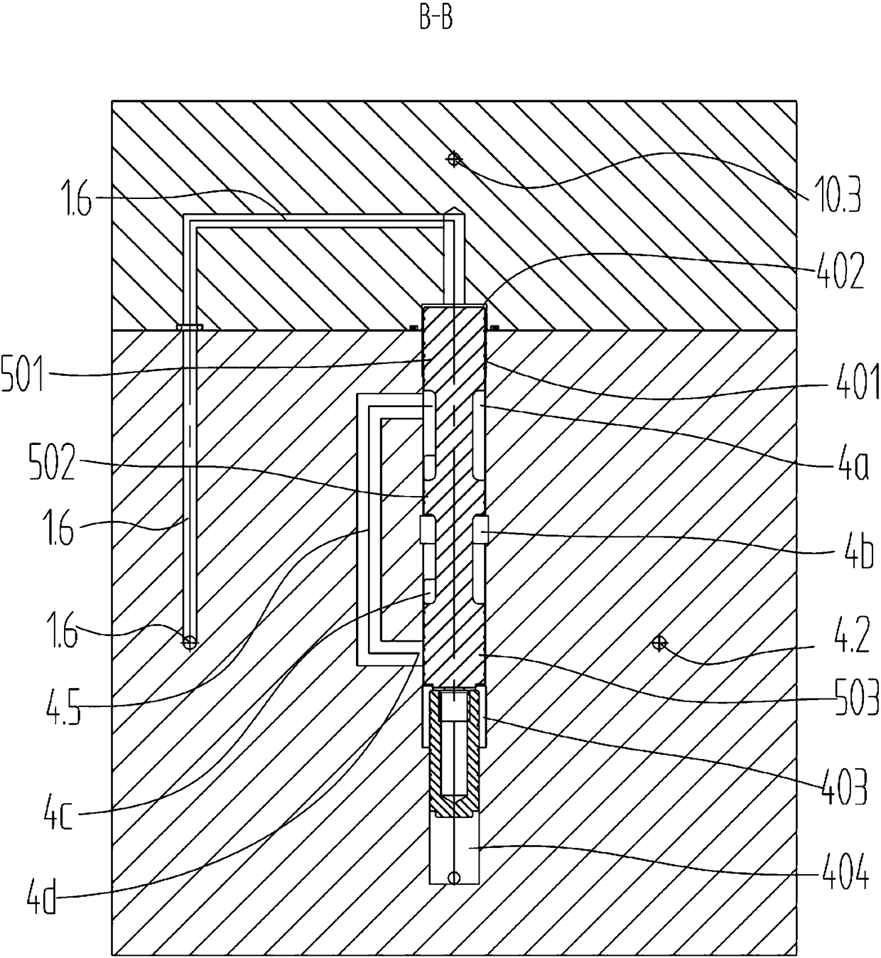
The invention discloses a hydraulic booster pump, which comprises a cylinder body internally and slidably connected with a piston. The left end of the cylinder body is provided with a left end cover and the right end of the cylinder body is provided with a right end cover; a plunger is slidably connected with the inner part of the left end cover; a valve hole is arranged in the right end cover. Afirst oil port, a second oil port, a third oil port and a fourth oil port are arranged in the right end cover. A valve core is slidably connected with the inner part of the valve hole. The lower end of the valve core is slidably connected with a control plunger and the cross sectional area of the control plunger is smaller than that of the valve core; the side surface of the valve core is providedwith a first shoulder, a second shoulder and a third shoulder; the upper end of the valve hole is provided with an upper end cover. An upper control cavity is formed between the first shoulder and the upper end cover. An oil return cavity is formed between the third shoulder and the upper end of the control plunger and the lower end of the valve hole. A lower control cavity is formed between thelower end of the control plunger and the right end cover; a liquid-controlled unloading valve assembly is arranged in the upper end cover; the booster pump has simple structure and no need of electriccontrol.

Description

technical field [0001] The invention relates to the technical field of booster pumps, in particular to a hydraulic booster pump capable of reliable automatic and continuous boosting. Background technique [0002] The hydraulic booster pump is an ultra-high pressure hydraulic component that amplifies the hydraulic pressure by using the principle that the two ends of the piston have different acting areas and the same force, and the hydraulic booster pump can increase the low pressure to 200MPa and above. At present, the traditional hydraulic booster pump used in China controls the reciprocating motion of the booster pump to continuously output high pressure through the continuous reversing of the electromagnetic reversing valve. The structure is complex, and complex displacement sensors and electronic control components need to be installed. Inconvenient to carry, difficult to use in flammable and explosive occasions and portable machinery, such as natural gas compression sub...

Claims


Application Information

Patent Timeline
Patent Type & Authority Applications(China)
IPC IPC(8): F04B9/103F04B53/00F04B53/10F15B3/00
CPCF04B9/103F04B53/00F04B53/10F15B3/00
Inventor 邵立坤
Owner 平湖必益清洁设备有限公司
Learn More