Detection device for oil-stolen orifice of pipeline and detection method of center and diameter of oil-stolen orifice

A detection device and pipeline technology, which is applied in the field of pipeline detection, can solve the problems of undetectable, characteristic signal disappearance, high lift-off value, etc., and achieve the effect of improving accuracy, low cost and improving maintenance efficiency

Active Publication Date: 2018-08-21
TIANJIN UNIV
View PDF15 Cites 1 Cited by
  • Summary
  • Abstract
  • Description
  • Claims
  • Application Information

AI Technical Summary

Problems solved by technology

However, this detection method has high requirements on the lift-off value. When the lift-off value is about 3mm, the characteristic signal basically disappears and cannot be detected.

Method used


Image

  • Detection device for oil-stolen orifice of pipeline and detection method of center and diameter of oil-stolen orifice
  • Detection device for oil-stolen orifice of pipeline and detection method of center and diameter of oil-stolen orifice
  • Detection device for oil-stolen orifice of pipeline and detection method of center and diameter of oil-stolen orifice

Examples


Embodiment 1

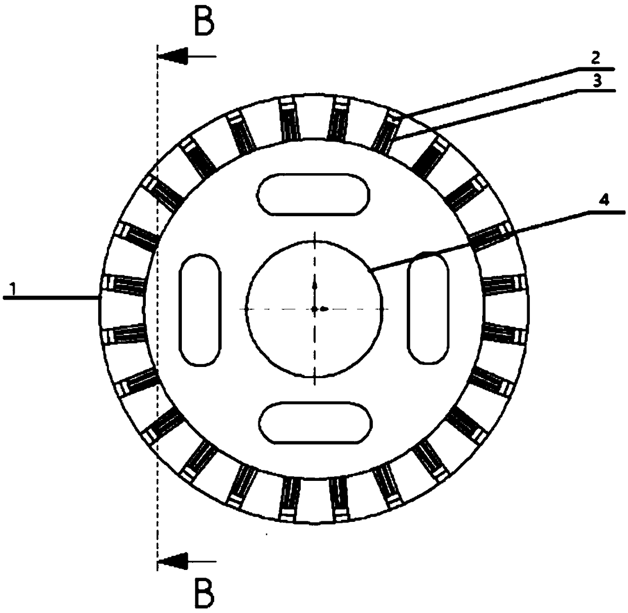
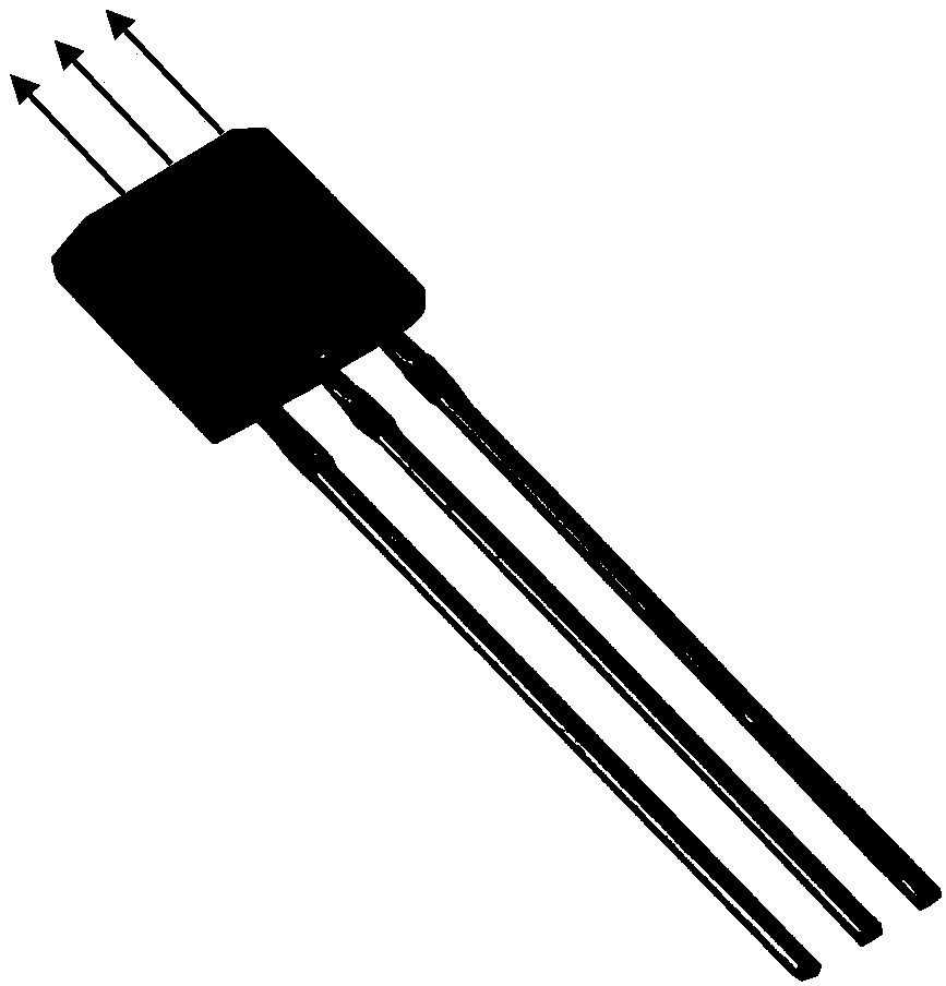
[0049] A detection device for pipeline oil stealing holes, see Figure 1-Figure 5 , the detection device includes: a detector 1 in the pipeline, a Hall element 2 and a magnet 5 are installed on the detector 1 in the pipeline (the embodiment of the present invention takes a cylindrical magnet 5 as an example for illustration, and during specific implementation, the embodiment of the present invention This is not limited), the model of the Hall element 2 used in this detection device is SS495A1, it has three pins, and its physical figure is as follows figure 2 shown.

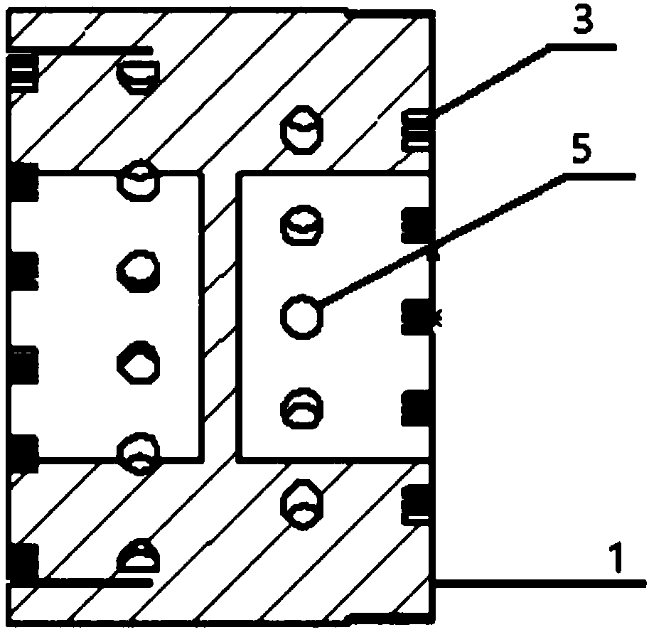
[0050] The front view and cross-sectional view of the detector 1 in the pipeline are as follows figure 1 and image 3 As shown: In order to avoid short circuit, each Hall element 2 is equipped with three pin slots 3 to respectively place the above three pins.

[0051] Such as image 3 As shown, the circular hole on the inner wall of the detector 1 in the pipeline is used to place a cylindrical magnet 5, and the...

Embodiment 2

[0054] The scheme in embodiment 1 is explained in principle below in combination with specific numerical values, see the following description for details:

[0055] The schematic diagram of the experimental device for the steel pipe test is shown in Figure 4 As shown: the detector 1 in the pipeline needs to be pushed forward by the pipeline fluid 13, and the wall of the device is attached to the wall of the pipeline.

[0056] In the in-pipe detector 1, the circumferential distance between the Hall elements 2 is 10-20mm, and the radius of the in-pipe detector 1 is equal to the inner diameter of the pipe.

[0057] The system block diagram of the detection device is as follows Figure 5 As shown: the battery 6 supplies power to the power management module 7, and the power supply to the Hall element 2 and the single-chip microcomputer 9 is realized through the power management module 7;

[0058] When the body of the pipeline detector 1 moves smoothly in the pipeline 11, under t...

Embodiment 3

[0064] Below in conjunction with concrete test, the scheme in embodiment 1 and 2 is carried out feasibility verification, see the following description for details:

[0065] The magnetic field signal detected by pushing the in-pipeline detector 1 into the pipeline 11 is as follows: Figure 7 shown.

[0066] Since the characteristic signal of the magnetic field of the oil stealing hole 12 has been determined, it can be distinguished from the test results that the Hall elements 22 and 23 just pass under the oil stealing hole 12, and the Hall element 21 and Hall element 24 just pass through the oil stealing hole. 12 pipe walls.

[0067] The size of the oil stealing hole 12 can also be estimated by the distance between the Hall element 21 and the Hall element 24 during field experiments, which is conducive to development and verification, that is, it is determined that the oil stealing hole 12 found is exactly the one detected by the detection device. oil hole.


PUM


Abstract

The invention discloses a detection device of an oil-stolen orifice of a pipeline and a detection method of the center and the diameter of an oil-stolen orifice. A Hall element and a magnet are arranged on the inner detector of the pipeline; each hall element is provided with three pin slots to respectively place the three pins; the round orifice on the inner wall of the inner detector of the pipeline is used for placing a magnet. The Hall element is vertically inserted into the three pin slots. The Hall element in the pin slot is arranged in parallel with the magnet in the round orifice. Thedistance between the Hall element and the magnet is greater than 2mm; the magnet can magnetize the pipe wall. When the detector in the pipeline passes through the oil-stolen orifice, due to the largerelative magnetic permeability of the oil-stolen orifice, the magnetic lines near the oil-stolen orifice are bent and changed. The Hall element receives the induced magnetic field signal, namely the magnetic field characteristic signal; According to the identification of the magnetic field characteristic signal, the defect condition of the pipeline is discriminated, the position of the defect of the pipeline is positioned, and pipeline maintenance is carried out. Meanwhile, the method also detects the center and the diameter of the oil-stolen orifice and improves the detection accuracy of theoil-stolen orifice.

Description

technical field [0001] The invention relates to the field of detection in pipelines, in particular to a detection device for a pipeline oil stealing hole and a detection method for the center and diameter of the oil stealing hole. Background technique [0002] Pipeline transportation is a special transportation mode of oil and gas resources. With the increasing demand for oil and gas resources in the economy and society, the pipeline transportation industry has become a huge industrial system, occupying an important strategic and economic position in the development of all countries in the world. With the continuous improvement of the pipeline transportation system, the length of the pipeline line continues to increase, and safety issues have been paid more and more attention. At the same time, how to detect the conditions in the pipeline to ensure the stable operation of the transportation system has become the focus of the industry. In recent years, driven by huge economi...

Claims


Application Information

Patent Timeline
Patent Type & Authority Applications(China)
IPC IPC(8): G01B7/12G01N27/83
CPCG01B7/12G01N27/83
Inventor 黄新敬燕玉田封皓李健陈世利曾周末
Owner TIANJIN UNIV
Why Eureka
Try Eureka