Busbar of high-rate discharging module

A high-rate discharge, busbar technology, applied in battery pack parts, circuits, electrical components, etc., can solve the problems of cell damage, laser welding virtual welding, high cost, etc., to save manpower and material resources, safe and stable performance, The effect of short processing time

Pending Publication Date: 2018-08-21
镇江科信动力系统设计研究有限公司
View PDF10 Cites 3 Cited by
  • Summary
  • Abstract
  • Description
  • Claims
  • Application Information

AI Technical Summary

Problems solved by technology

If a low-power laser welding machine is used, the thicker substrate cannot be penetrated and welded; if a high-power laser welding machine is selected, the thicker substrate of the busbar can be penetrated, but the heat during welding will cause damage to the battery core. Therefore, the common practice is to mill the welding position of the base material thinly. This process has great waste and loss in manpower, materials, equipment and other aspects. It is expensive, and it is not easy to mass-produce and automate production.
At the same time, the traditional flat busbar is not conducive to the complete fit of the busbar and the battery pole, and laser welding may cause virtual welding, which poses a safety hazard

Method used


Image

  • Busbar of high-rate discharging module
  • Busbar of high-rate discharging module
  • Busbar of high-rate discharging module

Examples


Embodiment 1

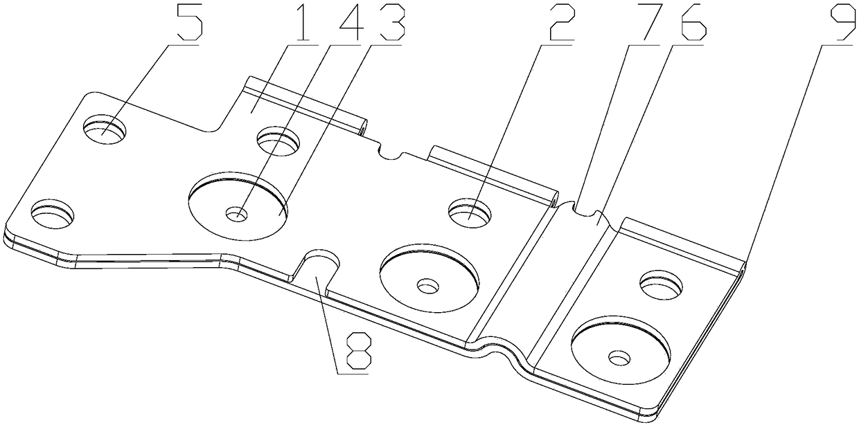
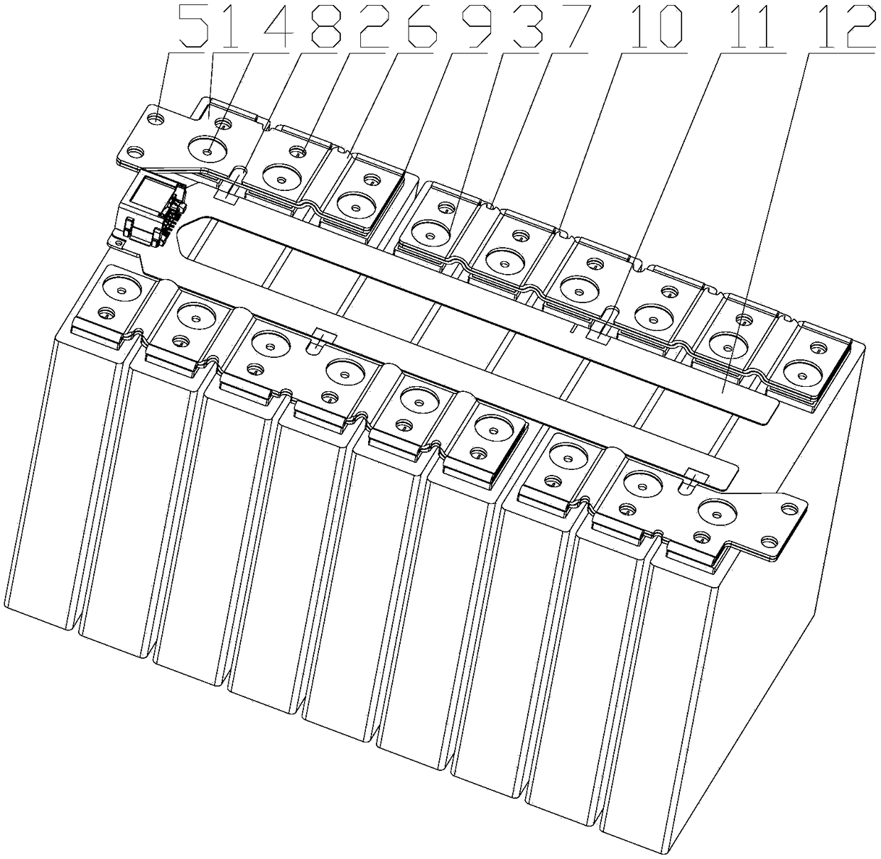
[0019] like Figure 1-2 As shown, the bus bar of a high-magnification discharge module uses aluminum as the base material. The aluminum material is first punched by a mold to form the cell polarity observation hole 2, the welding area hole 3, the welding observation hole 4, the fixing hole 5, Arched bending 6, positioning groove 7, and then the secondary mold completes the double-layer busbar body 1 after the substrate is folded in half, and the double-folded part of the substrate is a double-bend 9. The battery polarity observation hole 2 is opened through the two-layer base material of the bus bar body 1, and the position of the battery polarity observation hole 2 corresponds to the position of the battery pole mark. The first base material of the bus bar body 1 is provided with a welding area hole 3, the welding area hole 3 is circular, and the position of the welding area hole 3 corresponds to the position of the battery pole. The second layer base material of the bus bar ...

Embodiment 2

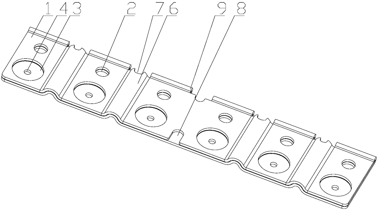
[0021] like Figure 2-3 As shown, the difference from Embodiment 1 is that there is no fixing hole 5 on the busbar body 1 for connecting different batteries 10 in the center of the module in series or in parallel. The invention is formed by two molds, the structure is ingenious, it is completely attached to the pole of the battery core, and the hidden danger of false welding is avoided. The utilization rate is compatible with various high and low power laser welding machines, and it has strong versatility, which is conducive to the realization of batch and automatic production.


PUM


Abstract

The invention discloses a busbar of a high-rate discharging module. The busbar comprise a busbar body, the busbar body is composed of two layers of base materials, battery-cell-polarity observing holes are formed in the two layers of base materials of the busbar body through penetrating, and positions of the battery-cell-polarity observing holes correspond to pole-column identification positions of battery cells; welding area holes are formed in the first layer of base material of the busbar body, positions of the battery-cell-polarity observing holes correspond to pole-column positions of thebattery cells, and welding observing holes are formed in the portions, located in the welding area holes, of the second layer of base material of the busbar body. The busbar has the advantages that the structure is ingenious, the busbar completely fits pole columns of the battery cells, laser welding welding is achieved, and the performance is safe and stable; the busbar is formed through stamping and bending of the single layer of base material, the cost is low, the requirement of the high-rate discharging module can be met, the processing labor hour is short, manpower and material resourcesare saved, dissipation is reduced, and batch and automatic production can be achieved.

Description

technical field [0001] The invention relates to the field of bus bars, in particular to a bus bar of a high rate discharge module. Background technique [0002] With the adjustment of the national new energy vehicle policy, the subsidy standard is gradually reduced compared with previous years. In the case of reduced state subsidies, in order to meet market demand, maintaining or reducing the price of complete vehicles will be the development trend of new energy vehicles in the future. Driven by such market requirements, while ensuring the normal functions of each component of the battery pack, the low cost of each component is currently a development direction that many manufacturers are vigorously researching. The bus bar is the basic conductor for the series and parallel connection between the cells. As one of the important parts of the electric vehicle battery pack, its importance is self-evident. How to ensure that the busbar can withstand high-rate and high-current p...

Claims


Application Information

Patent Timeline
Patent Type & Authority Applications(China)
IPC IPC(8): H01R25/16H01M2/20H01M2/22H01M50/505H01M50/528
CPCH01R25/16H01R25/161H01M50/528H01M50/502Y02E60/10
Inventor 王文斌吴永丰陈磊罗阳成
Owner 镇江科信动力系统设计研究有限公司
Why Eureka
Try Eureka