Self-excitation type hydraulic cleaning tool

A cleaning tool and self-excited technology, which is applied in cleaning methods and utensils, cleaning hollow objects, spraying devices, etc., can solve problems such as unsatisfactory effects, inability to clean in all directions, easy deposition of dirt, etc., and achieve efficient removal effect

Inactive Publication Date: 2018-08-24
四川大学锦城学院
View PDF0 Cites 8 Cited by
  • Summary
  • Abstract
  • Description
  • Claims
  • Application Information

AI Technical Summary

Problems solved by technology

[0002] The cleaning nozzles of the prior art cannot clean the pipeline in all directions. For some stubborn dirt, the effect of water cleaning is not ideal. Often after cleaning, there are still many dirt remaining on the inner wall of the pipeline; the dirt after cleaning is also easy to form deposits

Method used


Image

  • Self-excitation type hydraulic cleaning tool
  • Self-excitation type hydraulic cleaning tool
  • Self-excitation type hydraulic cleaning tool

Examples


specific Embodiment 1

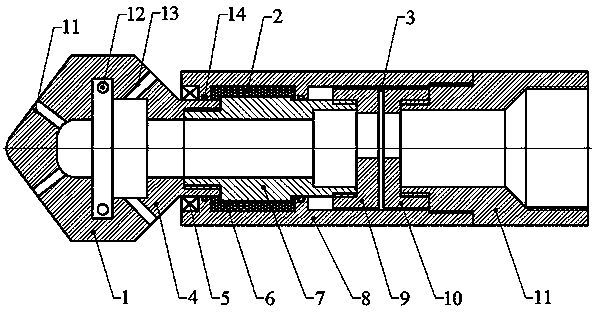
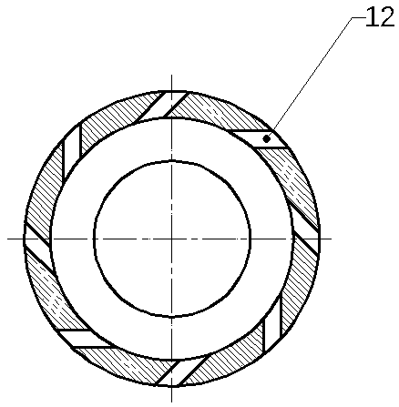
[0022] like figure 1 and figure 2 As shown, the present invention provides a self-excited hydraulic cleaning tool, including a spin mechanism 1 , a speed limiting mechanism 2 and a pulse mechanism 3 . Wherein the spin mechanism 1 includes a spin nozzle 4, the head of the spin nozzle 4 is provided with a forward hole 11, the side is provided with a tangential hole 12 and the side rear is provided with a rearward hole 13; the speed limiting mechanism 2 includes Outer casing 8, ball bearing 5 is installed on the outer circle of the tail of spin nozzle 4 and ball bearing 5 is installed and fixed on the inner side of outer casing 8, the interference fit between the outer casing 8 and ball bearing 5; There is a mandrel 7 with openings at both ends, two sets of sealing rings 14 are installed between the outer casing 8 and the mandrel 7, and the chamber 6 between the inner side of the outer casing 8, the outer side of the mandrel 7 and the sealing ring 14 is filled with viscous damp...

specific Embodiment 2

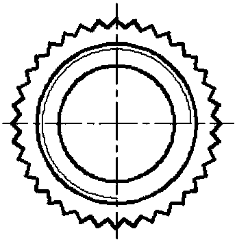
[0023] like image 3 As shown, on the basis of Embodiment 1, preferably, teeth are processed on the outer circle of the mandrel 7, and the height of the teeth is 5-7mm.

[0024] The effect of its improvement is that this technical feature can enhance the shear viscous damping fluid, and the resistance increases with the increase of the speed, which acts as a speed limiter, prevents the water flow from the nozzle from being scattered when the rotation speed is too high, and reduces the impact force.

[0025] It can be concluded that the jet nozzles in the above two embodiments generate forward jets to clean the dirt on the front end; the tangential jets clean the dirt on the circumference for a second time and generate tangential force to rotate the nozzles and form The swirling flow field can realize all-round cleaning; while the backward jet cleans the pipeline, the dirt is discharged backward. The pulse mechanism is that two eccentric holes move relative to each other. The ...


PUM


Abstract

The invention discloses a self-simulated hydraulic cleaning tool which comprises a spinning mechanism, a speed limiting mechanism and a pulse mechanism, wherein the spinning mechanism comprises a spinning nozzle; a forward hole is formed in the head of the spinning nozzle, a tangential hole is formed in the side surface of the spinning nozzle and a backward hole is formed in the rear portion of the spinning nozzle; the speed limiting mechanism comprises an outer housing; a mandrel with two open ends is mounted in the outer housing; two groups of sealing rings are mounted between the outer housing and the mandrel; a cavity among an inner side of the outer housing, an outer side of the mandrel and the sealing rings is injected with viscous damping fluid; the mandrel is connected with the spinning nozzle; the pulse mechanism comprises a rotary valve; the rotary valve is connected with the mandrel; an eccentric hole is processed in the rotary valve; a static valve is mounted on one side ofthe rotary valve; an eccentric hole is also processed in the static valve; the static valve is connected with an upper joint; and the upper joint is connected with the outer housing. The self-excitation type hydraulic cleaning tool has the benefits as follows: omnidirectional cleaning is achieved by forward jet flow, tangential jet flow and backward jet flow, and the capability of cleaning pipeline dirt is improved through internal hydraulic pulses.

Description

technical field [0001] The invention relates to the field of cleaning tools, in particular to a self-excited hydraulic cleaning tool. Background technique [0002] The cleaning nozzles of the prior art cannot clean the pipeline in all directions. For some stubborn dirt, the effect of water cleaning is not ideal. Often after cleaning, there are still many dirt remaining on the inner wall of the pipeline; the dirt after cleaning is also easy to form deposits. Contents of the invention [0003] In order to solve the above problems, the present invention proposes a self-activating hydraulic cleaning tool. [0004] In order to achieve the above object, the present invention adopts the following technical solutions: a self-excited hydraulic cleaning tool, including a spin mechanism, a speed limiting mechanism and a pulse mechanism, wherein: [0005] The spin mechanism includes a spin nozzle, the head of the spin nozzle is provided with a forward hole, the side is provided with ...

Claims


Application Information

Patent Timeline
Patent Type & Authority Applications(China)
IPC IPC(8): B08B9/032B05B1/14B05B1/34B05B5/04
CPCB08B9/0326B05B1/14B05B1/34B05B5/04B08B2209/024B08B2209/032
Inventor 简韬王樱蓓
Owner 四川大学锦城学院
Why Eureka
Try Eureka