
Processing robot

A technology of robots and processing chambers, applied in stone processing equipment, manipulators, working accessories, etc., can solve problems such as human injury, difficult distance adjustment, difficult operation, etc., and achieve the effect of convenient operation and simple structure

Inactive Publication Date: 2018-08-24
詹贺钫
View PDF0 Cites 0 Cited by
  • Summary
  • Abstract
  • Description
  • Claims
  • Application Information

AI Technical Summary

Problems solved by technology

The processing of stone requires drilling. The existing equipment for drilling stone is usually operated by manual hand-held drilling machine. In this way, the distance between each hole is difficult to adjust, the operation is difficult, and it will generate a lot of dust, which is harmful to the human body. cause some damages

Method used


Image

  • Processing robot
  • Processing robot
  • Processing robot

Examples


Embodiment Construction

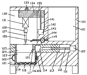
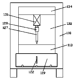
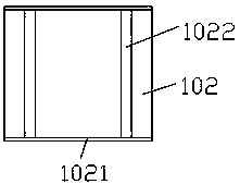
[0015] Combine below Figure 1-3 The present invention will be described in detail.

[0016] refer to Figure 1-3 , a processing robot according to an embodiment of the present invention includes a processing body 100, a processing cavity 132 is provided in the left end surface of the processing body 100, and a first Sliding cavity 111, the bottom wall of the first sliding cavity 111 communicates with the second sliding cavity 121, the first sliding cavity 111 and the second sliding cavity 121 respectively penetrate the left end surface of the processing body 100, the processing cavity In 132, a mounting block 134 is installed in sliding fit, and the bottom end of the mounting block 134 is fixedly provided with a drilling body 131, and the bottom end of the drilling body 131 is provided with a drill connector 128, which can be Drilling head 127 is installed on the disassembled part, and a lifting drive mechanism is mounted on the right end face of the mounting block 134. A s...


PUM


Abstract

The invention discloses a processing robot. The processing robot comprises a processing machine body, wherein a processing chamber is formed in the left side end surface of the processing machine body; a first sliding chamber which rightwards extends is formed in the bottom wall of the processing chamber in a communication manner; a second sliding chamber is formed in the bottom wall of the firstsliding chamber in a communication manner; the first sliding chamber and the second sliding chamber correspondingly pass through the left side end surface of the processing machine body; a mounting block is mounted in the processing chamber in a sliding fitting manner; a hole drilling machine body is fixedly arranged at the bottom end of the mounting block, and a drill bit connector is arranged atthe bottom end of the hole drilling machine body; a hole drill bit is detachably mounted in the bottom end of the drill bit connector; a lifting driving mechanism is mounted at the right side end surface of the mounting block in a power fitting manner; a sliding seat is mounted in the first sliding chamber in a sliding fitting manner; a clamping fixing chamber which penetrates the top and bottomis formed in the left side extending section of the sliding seat, and the clamping fixing chamber communicates with the processing chamber; and a pneumatic cylinder is fixedly arranged in the inner wall of the right side of the clamping fixing chamber.

Description

technical field [0001] The invention relates to the technical field of stone processing, in particular to a processing robot. Background technique [0002] At present, stone, as a high-grade building decoration material, is widely used in indoor and outdoor decoration design, curtain wall decoration and public facilities construction. At present, the common stone materials on the market are mainly divided into natural stone, artificial stone and marble. The processing of stone requires drilling. The existing equipment for drilling stone is usually operated by manual hand-held drilling machine. In this way, the distance between each hole is difficult to adjust, the operation is difficult, and it will generate a lot of dust, which is harmful to the human body. cause some damages. Contents of the invention [0003] The object of the present invention is to provide a processing robot for overcoming the above-mentioned defects in the prior art. [0004] A processing robot ac...

Claims


Application Information

Patent Timeline
Patent Type & Authority Applications(China)
IPC IPC(8): B28D1/14B28D7/00B28D7/02B25J11/00
CPCB28D1/14B25J11/005B28D1/146B28D7/00B28D7/005B28D7/02
Inventor 詹贺钫
Owner 詹贺钫
Learn More