Anti-leakage wastewater reaction equipment

A reaction equipment and anti-leakage technology, applied in water pollutants, water treatment parameter control, neutralized water/sewage treatment, etc. The effect of improving biochemical properties and improving the separation effect

Inactive Publication Date: 2018-08-24
HENAN CHANGMING HANGBIAO ELECTROMECHANICAL EQUIP CO LTD
View PDF0 Cites 1 Cited by
  • Summary
  • Abstract
  • Description
  • Claims
  • Application Information

AI Technical Summary

Problems solved by technology

[0009] In order to solve the problem of the small sewage treatment capacity of the integrated sewage treatment equipment in the prior

Method used


Image

  • Anti-leakage wastewater reaction equipment
  • Anti-leakage wastewater reaction equipment
  • Anti-leakage wastewater reaction equipment

Examples


Example Embodiment

[0043] Example 1

[0044] As a basic example:

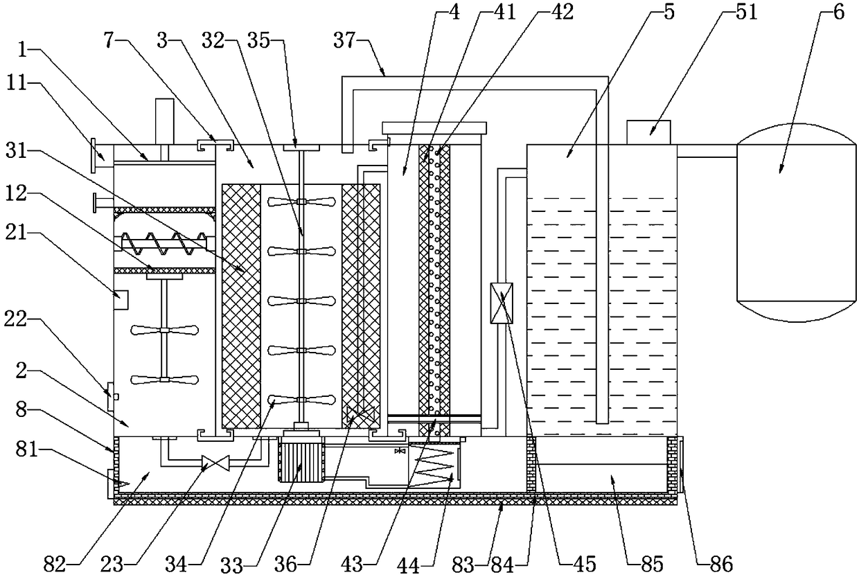
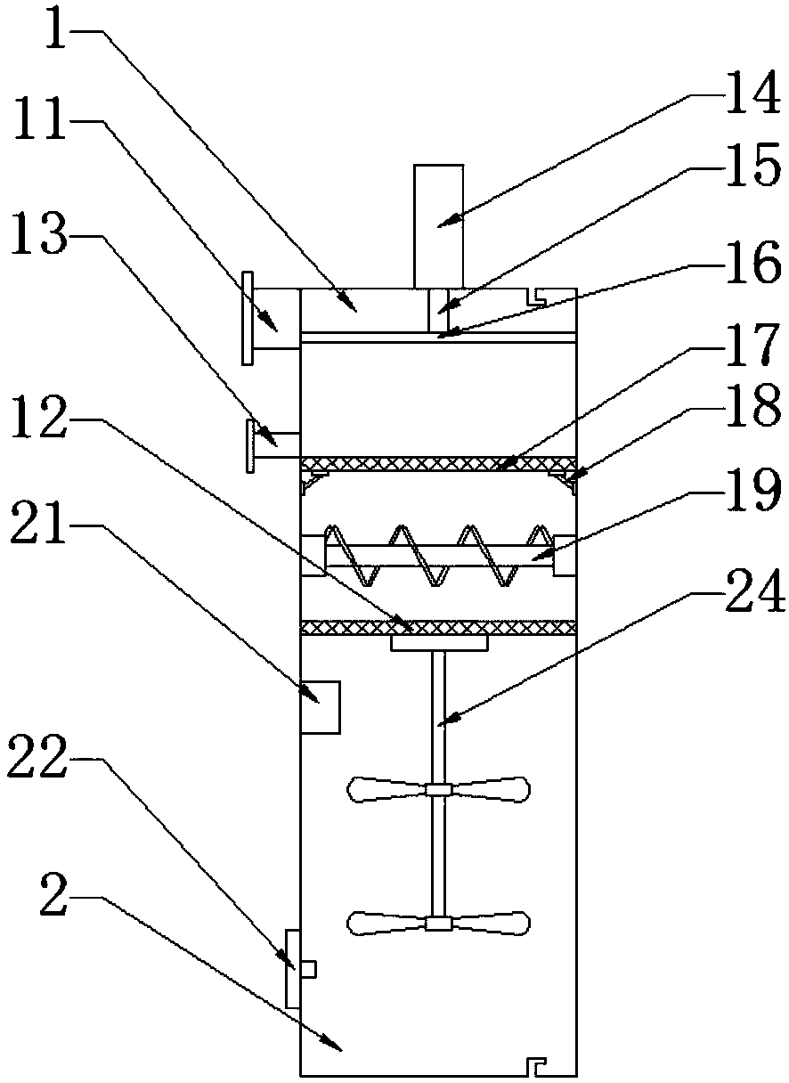
[0045] A kind of anti-leakage wastewater reaction equipment, including sedimentation well 1, regulating pond 2, anaerobic pond 3 and aerobic pond 4, described regulating pond 2 is connected with anaerobic pond 3, and described anaerobic pond 3 is connected with aerobic pond The tanks 4 are connected together, and it is characterized in that a hydraulic cylinder 14 is installed on the top surface of the settling well 1, and a hydraulic rod 15 located in the settling well 1 is connected under the hydraulic cylinder 14, and a hydraulic rod 15 is connected under the hydraulic rod 15. Filter plate 16, the inwall of sedimentation well 1 is equipped with the press filter screen 17 that is positioned at described press filter plate 16 below, and the inwall of the sedimentation well 1 below described press filter screen 17 is equipped with stirring separator 19, and described stirring A filter residue screen 12 is installed below the sep...

Example Embodiment

[0047] Example 2

[0048] This embodiment focuses on the improvements compared with the above-mentioned embodiments, and the similarities will not be repeated. In this embodiment, the top and bottom surfaces of the sedimentation well 1, the anaerobic pond 3, and the aerobic pond 4 are close to the pasting One side of the joint surface is provided with a clamping groove, and a clamping rubber strip 7 whose shape matches the clamping groove is installed in the clamping groove.

[0049] Further, the clamping rubber strip 7 is in a "concave" shape, and the ends of the two protruding parts of the "concave" shape of the clamping rubber strip 7 are connected with hooks extending toward the concave part of the clamping rubber strip 7 .

Example Embodiment

[0050] Example 3

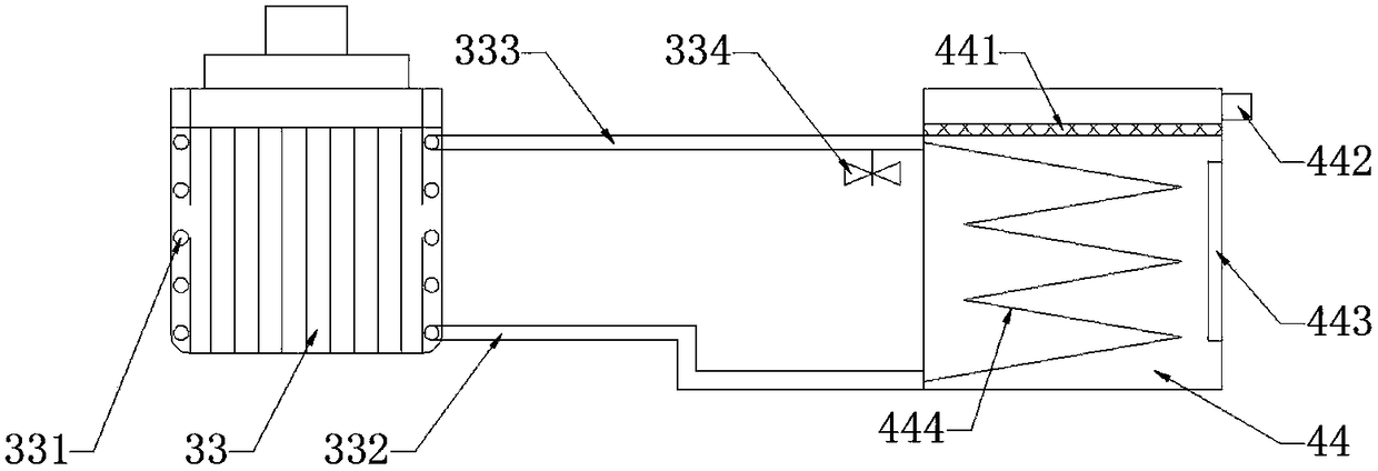
[0051] This embodiment focuses on the improvements compared with the above-mentioned embodiments, and the similarities will not be repeated. In this embodiment, the bottom surface of the anaerobic tank 3 is connected with a motor 33 connected to the stirring shaft 32, so Said motor 33 is provided with a spiral heat exchange tube 331, the bottom of the aerobic pool 4 is connected with an antifreeze fan 44, a heating tube 444 is installed in the antifreeze fan 44, and the upper and lower ends of the heating tube 444 are respectively connected with a spiral The upper end of the heat exchange pipe 331 is connected to the liquid outlet pipe 333 and the liquid inlet pipe 332 connected to the upper end. The liquid outlet pipe 333 is connected with an antifreeze valve 334, and a heating net 441 is installed above the antifreeze fan 44. A thermometer 442 is connected above the side, and an inspection door 443 is also installed on the side of the antifreeze fan 44 . ...


PUM


Abstract

The invention discloses anti-leakage wastewater reaction equipment and belongs to the technical field of electromechanical devices. The problem in the prior art that integrated sewage treatment equipment is small in sewage treatment quantity is solved. The anti-leakage wastewater reaction equipment disclosed by the invention comprises a settling basin, a regulating reservoir, an anaerobic pool, anaerobic tank and a leakage protection device, wherein a filter pressing plate is arranged in the settling basin; a filter pressing net positioned below the filter pressing plate is arranged on the inner wall of the settling basin; a stirring separator is arranged on the inner wall of the settling basin below the filter pressing net; a filter residue net is arranged below the stirring separator; anaerobic packing is filled in the anaerobic pool; a stirring shaft is arranged in the anaerobic packing; an anti-freezing fan is connected to the bottom of the aerobic tank; the leakage protection device comprises a sewage tank; a reduction reaction layer is arranged on the inner wall of the leakage protection device; a pH value probe is connected onto the inner wall of the sewage tank; an activated carbon layer is connected below the leakage protection device. The anti-leakage wastewater reaction equipment disclosed by the invention is capable of rapidly treating sewage and large in treatmentquantity and has a leakage protection function.

Description

technical field [0001] The invention belongs to the technical field of electromechanical equipment, and in particular relates to an anti-leakage wastewater reaction equipment. Background technique [0002] With the rapid development of cities in our country, the urban population is increasing rapidly, and the urban water consumption is increasing rapidly. There is a large gap in my country's sewage treatment industry, and the environmental situation is still severe. The problem between sewage discharge and environmental protection is a protracted war. Due to the complex process and large processing capacity, the existing sewage treatment equipment is usually complex in structure and bulky, and is divided into multiple equipment for separate installation according to the process. Sewage treatment plants create enormous economic pressure, which is not conducive to sustainable development. [0003] Therefore, the transformation of the sewage treatment system from large-scale c...

Claims


Application Information

Patent Timeline
IPC IPC(8): C02F9/14C02F101/30
CPCC02F9/00C02F1/001C02F1/66C02F3/30C02F2101/30C02F2209/06C02F2303/04
Inventor 任延超
Owner HENAN CHANGMING HANGBIAO ELECTROMECHANICAL EQUIP CO LTD
Why Eureka
Try Eureka