Inclined outer ring plate fabricated cross connecting beam-column joint

A cross-connection and beam-column node technology, applied in columns, pillars, piers and other directions, can solve the problems of inconvenient transportation and construction, large welding workload, and inability to guarantee welding quality, and achieve convenient and fast installation, reduce transportation costs, The effect of improving transportation efficiency and construction efficiency

Active Publication Date: 2018-08-24
QINGDAO TECHNOLOGICAL UNIVERSITY
View PDF10 Cites 11 Cited by
  • Summary
  • Abstract
  • Description
  • Claims
  • Application Information

AI Technical Summary

Problems solved by technology

Since the outer ring plate is easily damaged during transportation, it needs to be welded with the steel beam flange plate on site, resulting in a large welding workload on site and the welding quality cannot be guaranteed, making transportation and construction inconvenient

Method used


Image

  • Inclined outer ring plate fabricated cross connecting beam-column joint
  • Inclined outer ring plate fabricated cross connecting beam-column joint
  • Inclined outer ring plate fabricated cross connecting beam-column joint

Examples


Embodiment 1

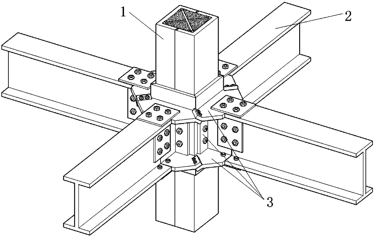
[0051] like figure 1 As shown, the inclined outer ring plate assembled cross connection beam-column node of the present invention includes a square steel tube column 1, an H-shaped steel beam 2 and a beam-column connection assembly 3 connecting the two;

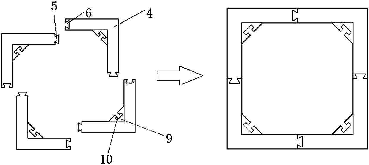
[0052] like figure 2 As shown, the square steel pipe column is spliced ​​by four identical L-shaped columns 4, and each L-shaped column is provided with splicing joints 5 and splicing grooves 6 at both ends, and the splicing joints of the four L-shaped columns match the splicing grooves Assembled into a square steel pipe column;

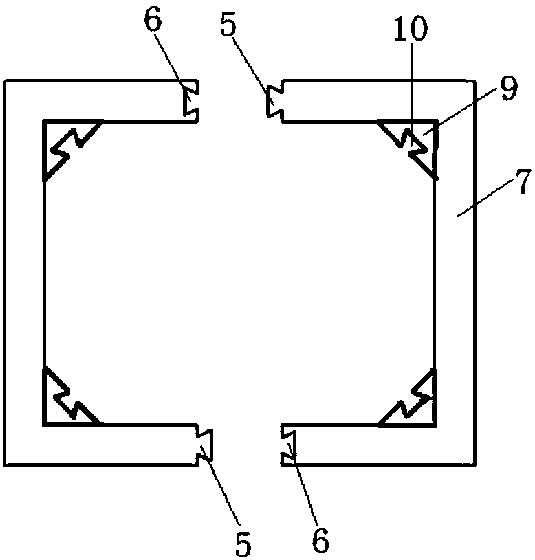
[0053] Based on L-shaped columns, various splicing methods of square steel pipe columns can be derived. For example, square steel pipe columns are spliced ​​by two identical C-shaped columns 7, and each C-shaped column is composed of two L-shaped columns. A splicing joint and a splicing groove are respectively provided at both ends of a C-shaped column, and the splicing joints and splicing grooves ...

Embodiment 2

[0072] like Figure 13 As shown, the difference between this embodiment and Embodiment 1 is that the cross-shaped connecting keel is replaced by a round tube combined keel 29, and the round tube combined keel includes a round steel pipe 30 in the middle and four connecting side plates, and the four connecting side plates are evenly distributed Around the round steel column, the adjacent connecting side plates are perpendicular to each other. The connecting side plates have the same structure as the connecting side plates in Embodiment 1, and the ends are also provided with plug joints matching the socket holes. As a result, the square steel pipe column becomes a sleeve-type steel pipe column, and the inner and outer steel pipes replace the steel bars and have a restraining effect on the concrete. The overall component has the characteristics of high bending rigidity, light weight, good seismic performance and good fire resistance, and is suitable for viaducts. Piers, supportin...

Embodiment 3

[0074] The difference between this embodiment and Embodiment 1 is that each group of miter plates includes two identical half-envelope miter plates 31, and each half-envelope miter plate is connected by two adjacent standard miter plates in Embodiment 1. The plates are integrated into one body, retaining the upward sloping and downward sloping lugs at both ends. like Figure 14 shown.

[0075] The two-in-one splicing plate can be slid in from one of two directions, so one of the original two T-shaped sliders on each splicing plate can be retained, and the other can be removed. The T-shaped chute on the connecting piece is reserved, and there is no need to set the T-shaped chute on the other T-shaped connecting pieces. The semi-enclosed splicing panels are also prefabricated in advance in the factory as standard parts, and can be assembled on site. Others are the same as in Example 1.


PUM


Abstract

The invention relates to the technical field of connection of building structures, and discloses an inclined outer ring plate fabricated cross connecting beam-column joint. The inclined outer ring plate fabricated cross connecting beam-column joint comprises a square steel tube column, H-shaped steel beams and beam-column connecting assemblies. Each beam-column connecting assembly comprises two groups of miter plates and T-shaped connecting pieces, wherein the two groups of miter plates are arranged symmetrically in a up and down mode; each group of miter plates comprises four identical standard miter plates, each standard miter plate comprises a horizontal part, a vertical part and connecting lugs, and a T-shaped sliding piece is arranged on the back surface of each horizontal part. The T-shaped connecting pieces are provided with T-shaped sliding grooves matched with the T-shaped sliding pieces. According to the inclined outer ring plate fabricated cross connecting beam-column joint,the miter plates are used as standard splicing pieces, the integrity of an outer ring plate is ensured while the strength of a joint area is ensured, the outward movement of plastic hinges is realized, the miter plates provide sufficient construction space, the installation is convenient, and the miter plates can be replaced in time after being damaged; and welding of all components is completedin a factory, the connection is completely carried out through bolts on site, the completely fabricated construction is realized, the quality problems caused by site welding are avoided, and the construction progress is speeded up.

Description

technical field [0001] The invention relates to the technical field of connection of building structures, in particular to a cross-connected beam-column joint of an assembled cross-connected inclined outer ring plate. Background technique [0002] Steel structure buildings have the characteristics of high strength, light weight, fast construction speed, good seismic performance and high degree of industrialization. Steel structural components form a structural system by connecting nodes, and the choice of node form has a direct impact on structural integrity, reliability, construction period, and the design and construction of auxiliary components. [0003] The outer ring plate joint is a common joint form, mainly composed of ring plate, web shear connection plate, steel pipe column, steel beam and so on. The connection form of the steel pipe column and the steel beam is generally bolted and welded. In actual engineering applications, it is generally necessary to weld the s...

Claims


Application Information

Patent Timeline
Patent Type & Authority Applications(China)
IPC IPC(8): E04B1/24E04B1/58E04C3/32
CPCE04B1/2403E04B1/5812E04B1/5831E04B2001/2406E04B2001/2454E04C3/32
Inventor 牟犇王君昌班慧勇刘芸郭念涵
Owner QINGDAO TECHNOLOGICAL UNIVERSITY
Why Eureka
Try Eureka