Beam-to-column joint of cross-connected beam-to-column joint with inclined outer ring plate
A cross-connection, beam-column joint technology, applied in columns, pillars, piers and other directions, can solve the problems of unguaranteed welding quality, large welding workload, inconvenient transportation and construction, etc., to improve transportation efficiency and construction efficiency, reduce Transportation cost, convenient and quick installation
- Summary
- Abstract
- Description
- Claims
- Application Information
AI Technical Summary
Problems solved by technology
Method used
Image
Examples
Embodiment 1
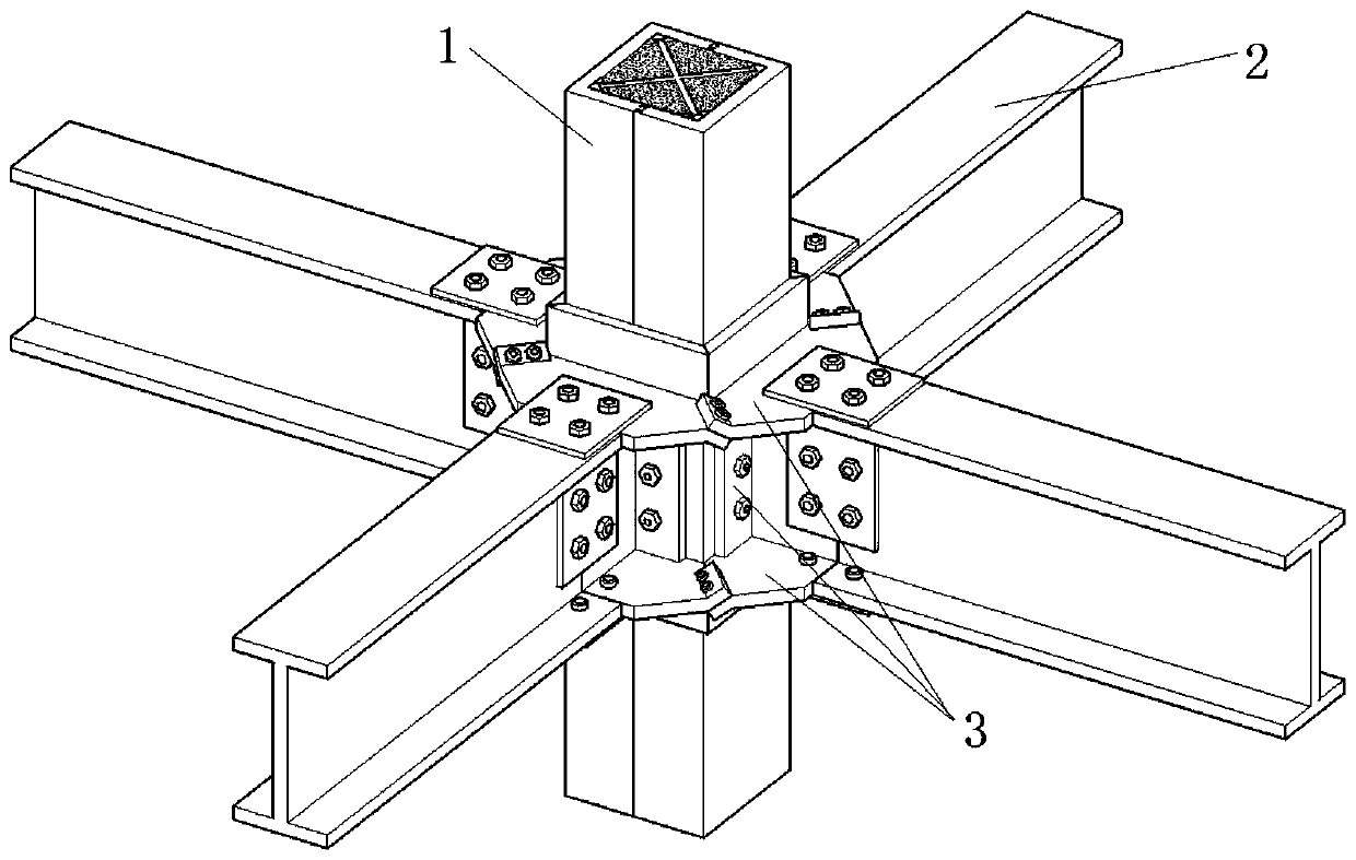
[0051] Such as figure 1 As shown, the inclined outer ring plate assembled cross connection beam-column node of the present invention includes a square steel tube column 1, an H-shaped steel beam 2 and a beam-column connection assembly 3 connecting the two;
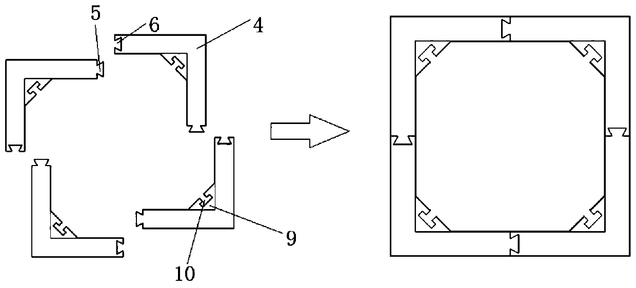
[0052] Such as figure 2 As shown, the square steel pipe column is spliced by four identical L-shaped columns 4, and each L-shaped column is provided with splicing joints 5 and splicing grooves 6 at both ends, and the splicing joints of the four L-shaped columns match the splicing grooves Assembled into a square steel pipe column;
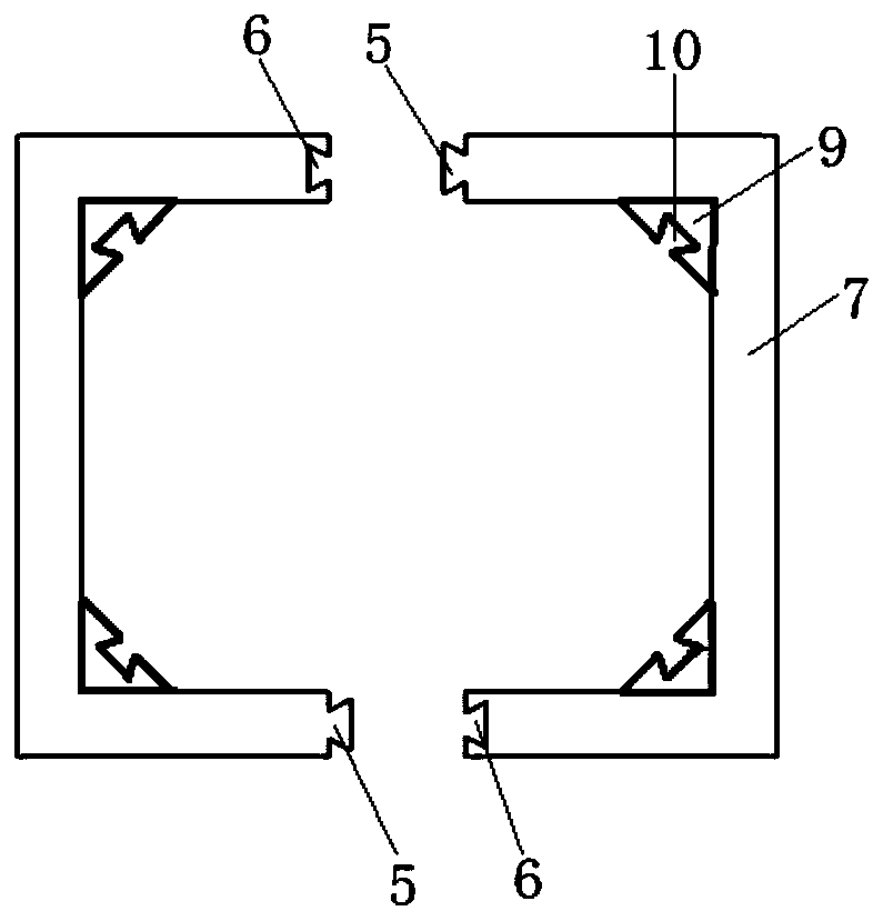
[0053] Based on L-shaped columns, various splicing methods of square steel pipe columns can be derived. For example, square steel pipe columns are spliced by two identical C-shaped columns 7, and each C-shaped column is composed of two L-shaped columns. A splicing joint and a splicing groove are respectively provided at both ends of a C-shaped column, and the splicing joints and splicing gr...
Embodiment 2
[0072] Such as Figure 13 As shown, the difference between this embodiment and Embodiment 1 is that the cross-shaped connecting keel is replaced by a round tube combined keel 29, and the round tube combined keel includes a round steel pipe 30 in the middle and four connecting side plates, and the four connecting side plates are evenly distributed Around the round steel column, the adjacent connecting side plates are perpendicular to each other. The connecting side plates have the same structure as the connecting side plates in Embodiment 1, and the ends are also provided with plug joints matching the socket holes. As a result, the square steel pipe column becomes a sleeve-type steel pipe column, and the inner and outer steel pipes replace the steel bars and have a restraining effect on the concrete. The overall component has the characteristics of high bending rigidity, light weight, good seismic performance and good fire resistance, and is suitable for viaducts. Piers, suppor...
Embodiment 3
[0074] The difference between this embodiment and Embodiment 1 is that each group of miter plates includes two identical half-envelope miter plates 31, and each half-envelope miter plate is connected by two adjacent standard miter plates in Embodiment 1. The plates are integrated into one body, retaining the upward sloping and downward sloping lugs at both ends. Such as Figure 14 shown.
[0075] The two-in-one splicing plate can be slid in from one of two directions, so one of the original two T-shaped sliders on each splicing plate can be retained, and the other can be removed. The T-shaped chute on the connecting piece is reserved, and there is no need to set the T-shaped chute on the other T-shaped connecting pieces. The semi-enclosed splicing panels are also prefabricated in advance in the factory as standard parts, and can be assembled on site. Others are the same as in Example 1.
PUM
 Abstract
Description
Claims
Application Information
 - R&D
- Intellectual Property
- Life Sciences
- Materials
- Tech Scout
- Unparalleled Data Quality
- Higher Quality Content
- 60% Fewer Hallucinations
Browse by: Latest US Patents, China's latest patents, Technical Efficacy Thesaurus, Application Domain, Technology Topic, Popular Technical Reports.
© 2025 PatSnap. All rights reserved.Legal|Privacy policy|Modern Slavery Act Transparency Statement|Sitemap|About US| Contact US: help@patsnap.com


