Control devices for electronic products
A technology of control devices and electronic products, which is applied in the direction of amplification control, electrical components, and limit amplitude, etc., and can solve problems such as signal instability, signal disorder, and affecting user experience
- Summary
- Abstract
- Description
- Claims
- Application Information
AI Technical Summary
Problems solved by technology
Method used
Image
Examples
Embodiment 1
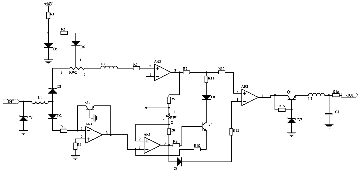
[0013] Embodiment 1. A control device for an electronic product includes a signal receiving circuit, a logarithmic differential feedback circuit, and a comparative voltage-stabilizing output circuit. The signal receiving circuit receives a signal at the input end of a signal transmission channel in the control device for an electronic product, and the logarithm The differential feedback circuit is divided into two channels to receive the signal output from the signal receiving circuit. One channel is input into the non-inverting input terminal of the operational amplifier AR2 after being limited by the sliding rheostat RW2. At the same time, the +10V power supply provides the base potential for the non-inverting input terminal of the operational amplifier AR2. The other path is processed by the logarithmic circuit composed of the operational amplifier AR4 and the transistor Q1. The signals output by the logarithmic circuit are the base potential of the inverting input terminal o...
Embodiment 2
[0015] Embodiment 2, on the basis of Embodiment 1, the signal receiving circuit receives the signal at the input end of the signal transmission channel in the control device of the electronic product, the voltage regulator tube D1 has the effect of voltage regulation, the inductance L1 filters, and one end of the inductance L1 Connect the diode D3 and the anode of the diode D2, the other end of the inductor L1 is connected to the signal output port and the cathode of the Zener tube D1, and the anode of the Zener tube D1 is grounded.
[0016]Implementation three, on the basis of the first embodiment, the comparison voltage regulator output circuit receives the output signal of the logarithmic differential feedback circuit, the comparator AR3 compares the signal, and a voltage regulator circuit composed of a transistor Q3 and a voltage regulator tube D7 is designed to regulate the voltage , further stabilize the signal, and design the LC circuit composed of the inductor L2 and th...
PUM
 Abstract
Description
Claims
Application Information
 - R&D
- Intellectual Property
- Life Sciences
- Materials
- Tech Scout
- Unparalleled Data Quality
- Higher Quality Content
- 60% Fewer Hallucinations
Browse by: Latest US Patents, China's latest patents, Technical Efficacy Thesaurus, Application Domain, Technology Topic, Popular Technical Reports.
© 2025 PatSnap. All rights reserved.Legal|Privacy policy|Modern Slavery Act Transparency Statement|Sitemap|About US| Contact US: help@patsnap.com


