Eureka AIR delivers breakthrough ideas for toughest innovation challenges, trusted by R&D personnel around the world.

Vehicle anti-lock control system and slip ratio vibration suppression method based on LQG controller

A jitter suppression and anti-lock technology, applied in general control systems, control/regulation systems, brakes, etc., to solve problems such as decreased control effect, inability of hydraulic units to accurately execute control commands, and excessive wheel slip rate jitter.

Active Publication Date: 2018-08-28
GUANGZHOU XIHE AUTOMOBILE ELECTRONICS DEVICES
View PDF7 Cites 1 Cited by
  • Summary
  • Abstract
  • Description
  • Claims
  • Application Information

AI Technical Summary

Problems solved by technology

However, in actual engineering applications, the control torque signal output by the LQG controller needs to be realized through the brake pressure adjustment device of the hydraulic unit, which is subject to the oil pressure, friction consumption, and the output from the applied brake pressure to the actual brake torque. Due to a certain time delay and other reasons, the hydraulic unit cannot accurately execute the control instructions issued by the LQG controller, which eventually leads to a decline in the control effect of ABS in executing vehicle anti-lock braking control.
After research and analysis, it is found that when the LQG controller is used to control the hydraulic unit to perform anti-lock braking control, sometimes the phenomenon of excessive vibration of the wheel slip rate may occur

Method used


Image

  • Vehicle anti-lock control system and slip ratio vibration suppression method based on LQG controller
  • Vehicle anti-lock control system and slip ratio vibration suppression method based on LQG controller
  • Vehicle anti-lock control system and slip ratio vibration suppression method based on LQG controller

Examples


Embodiment Construction

[0021] The invention will be further described in detail below in conjunction with the accompanying drawings and specific embodiments.

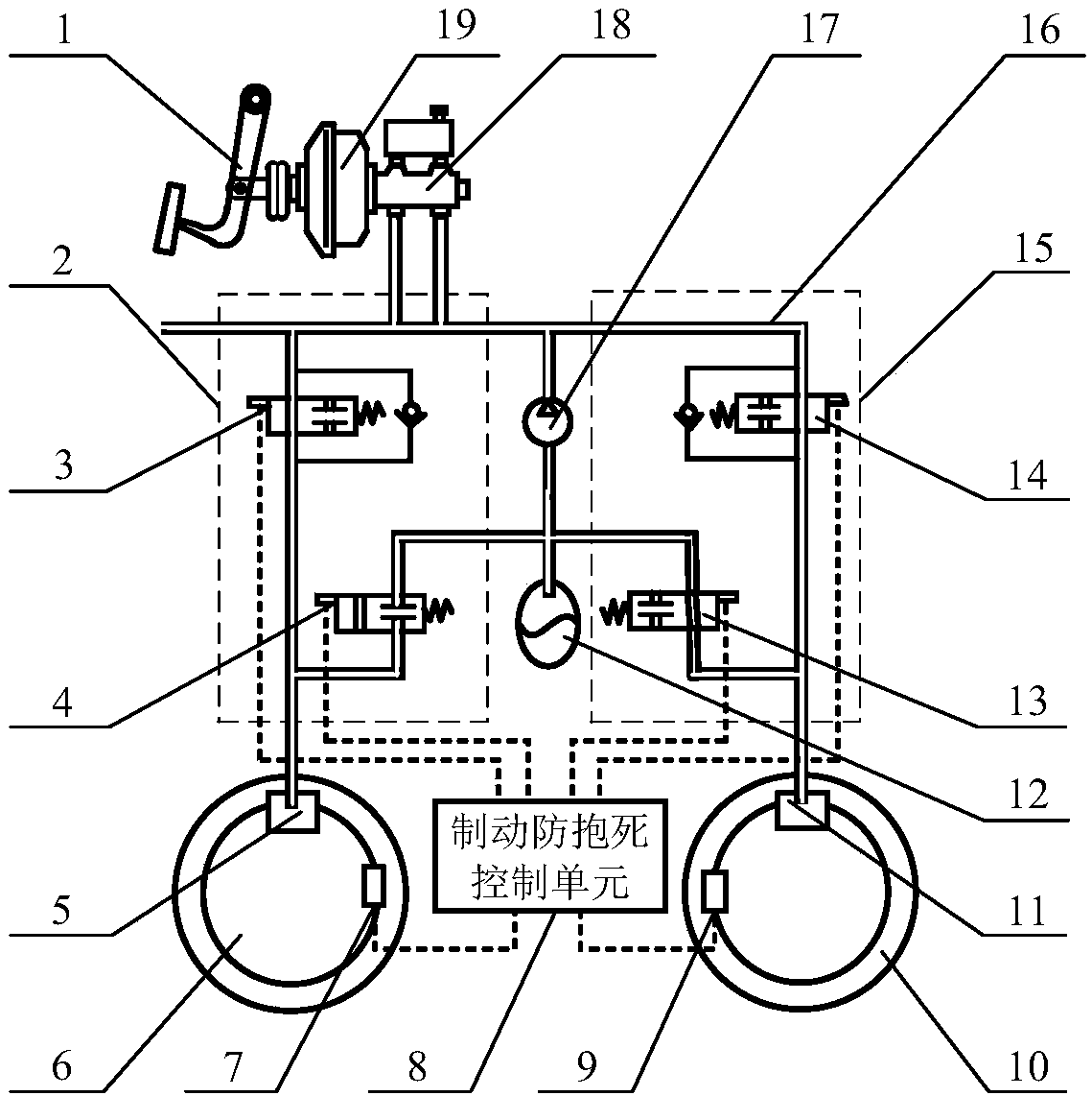
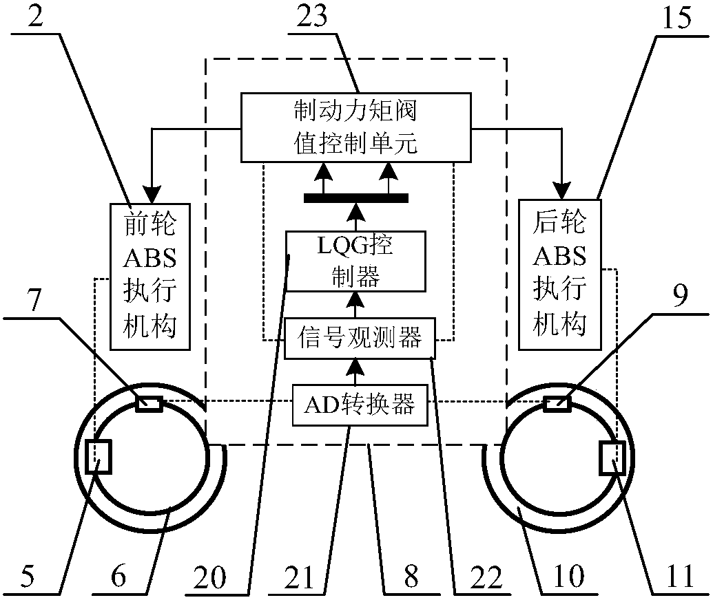
[0022] Such as figure 1 As shown, the vehicle anti-lock brake control system includes a brake pedal 1, a front wheel cylinder 5, a front wheel 6, a front wheel speed sensor 7, a brake anti-lock brake control unit 8, a rear wheel speed sensor 9, a rear wheel 10. Rear wheel cylinder 11, brake fluid accumulator 12, oil pipe 16, return pump 17, brake master cylinder with oil reservoir 18, brake booster 19, front wheel ABS actuator 2 and rear wheel ABS Executing mechanism 15; wherein the front wheel ABS actuator 2 includes two parts, the front wheel liquid inlet valve 3 and the front wheel liquid outlet valve 4, and the rear wheel ABS actuator 15 includes two parts: the rear wheel liquid outlet valve 13 and the rear wheel liquid inlet valve 14. The brake pedal 1 is connected to one end of the brake booster 19, and the other end of the brake boost...


PUM


Abstract

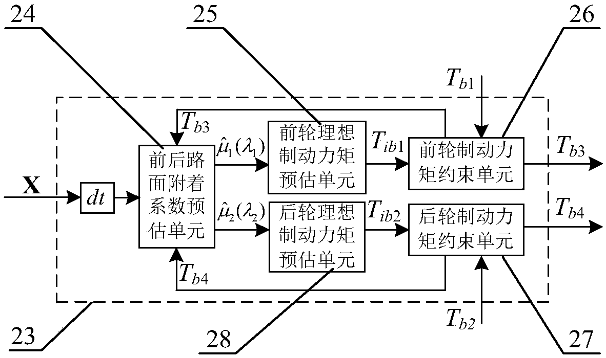
The invention discloses a vehicle anti-lock control system and slip ratio vibration suppression method based on an LQG controller. By designing a brake torque threshold control unit, the output braketorque range output by a brake anti-lock control unit is subjected time-varying limiting, and the brake torque threshold control unit is composed of front and rear road surface adhesion coefficient estimation units, front and rear wheel ideal brake torque estimation units and front and rear wheel brake torque constraint units. The brake torque range is limited in the following control steps that 1, the front and rear road surface adhesion coefficient estimation units estimate front and rear road surface adhesion coefficients; 2, the front and rear wheel ideal brake torque estimation units determine front and rear wheel ideal brake torques through the polynomial fitting relation between the road surface adhesion coefficients and the brake torques; 3, upper and lower limit thresholds of thefront and rear wheel brake torques are set, so that the brake torques output by the LQG controller are subjected to limit constraint of the upper and lower limit thresholds, and then actual control signals of the brake torques output by the brake anti-lock control unit are obtained.

Description

technical field [0001] The invention belongs to the technical field of wheel slip rate control during vehicle braking, and in particular relates to a vehicle anti-lock braking control system based on an LQG controller and a slip rate shake suppression method. Background technique [0002] Vehicle anti-lock braking system (ABS) is an active safety control system that can prevent the car from locking and slipping during braking. Vehicles equipped with ABS make the wheels always in a better braking state, ensuring that the vehicle has a certain steering ability during the braking process, thereby improving the braking stability of the vehicle and reducing the risk of the vehicle under emergency braking conditions. probability of traffic accidents. [0003] As one of the core technologies in ABS, the slip rate control method plays a decisive role in the braking performance of the vehicle. Common slip rate control methods mainly include: PID control, sliding mode variable struc...

Claims


Application Information

Patent Timeline
IPC IPC(8): B60T8/174G05B13/04
CPCB60T8/174G05B13/042
Inventor 何仁王骏骋
Owner GUANGZHOU XIHE AUTOMOBILE ELECTRONICS DEVICES
Why Eureka
Eureka Blog
Learn More