Automatic sludge processing device and method

An automatic sludge treatment technology, applied in sludge treatment, water/sludge/sewage treatment, dehydration/drying/concentrated sludge treatment, etc., can solve problems such as undiscovered fast and convenient methods, and achieve screening Good effect, avoid secondary mixing, high degree of automation

Inactive Publication Date: 2018-08-28
浙江明境环保科技集团有限公司
View PDF1 Cites 4 Cited by
  • Summary
  • Abstract
  • Description
  • Claims
  • Application Information

AI Technical Summary

Problems solved by technology

[0006] However, the inventors have found in practice that no quick and convenient method has been found for the treatment of magnetic metals and removal of water in the sludge produced by domestic sewage plants.

Method used


Image

  • Automatic sludge processing device and method
  • Automatic sludge processing device and method
  • Automatic sludge processing device and method

Examples


Embodiment 1

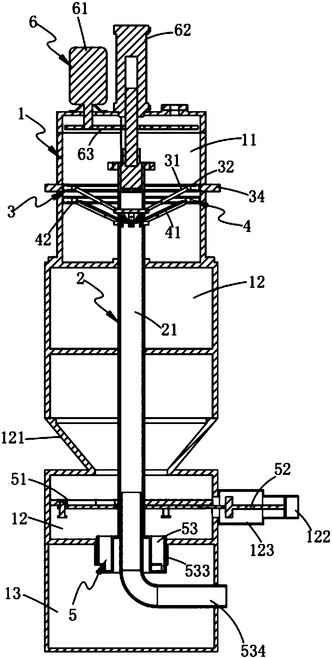
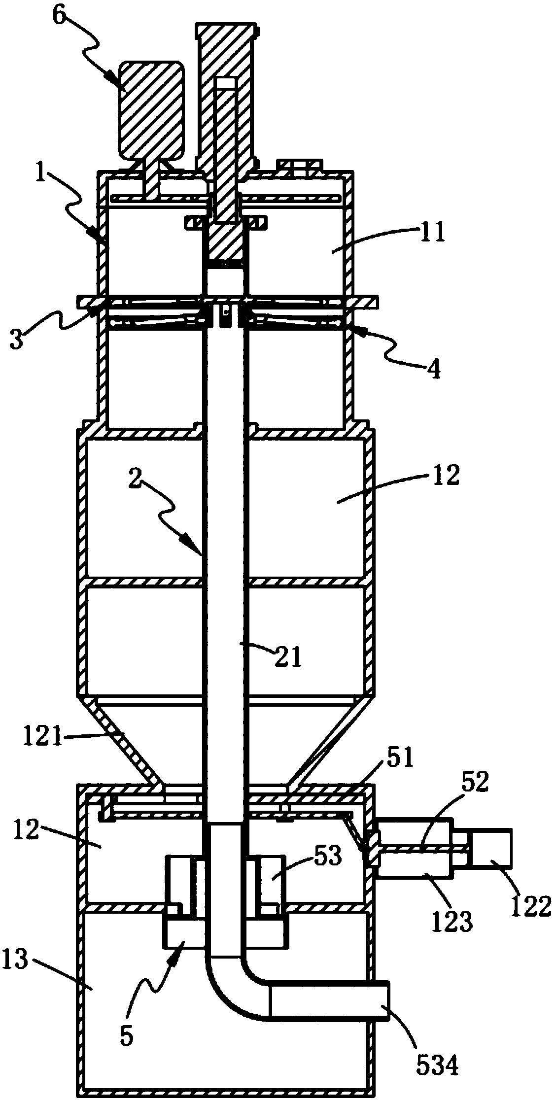
[0069] Such as figure 1 versus figure 2 As shown, an automatic screening and dewatering device for sludge impurities includes a processing box 1, which is divided into a sieve zone 11, a stratification zone 12, and an output zone 13 from top to bottom, and further includes:

[0070] The main shaft 2, the main shaft 2 is vertically rotatably arranged in the processing box 1, and is hollowed out, and a channel 21 is provided inside;

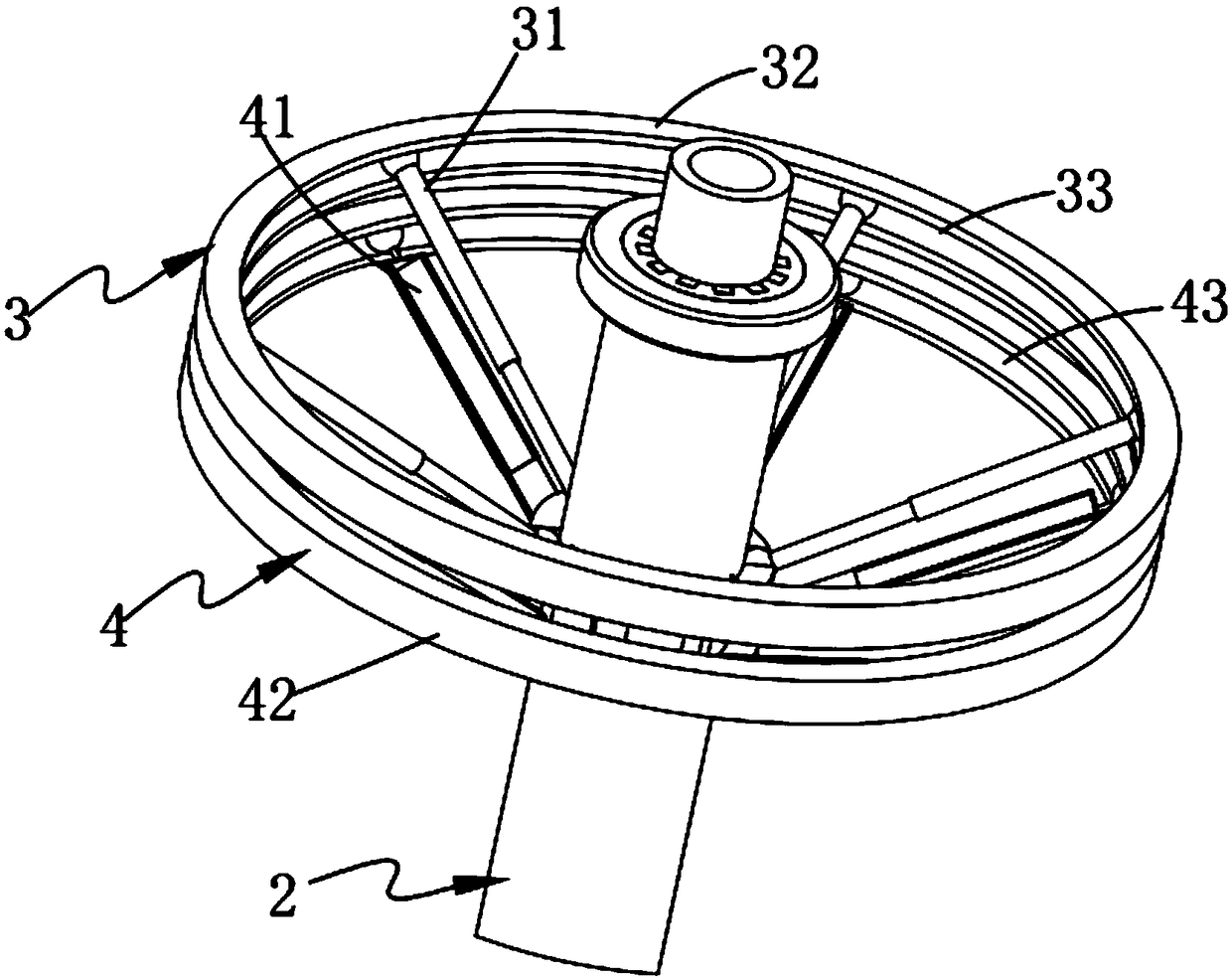
[0071] The screening mechanism 3 is arranged in the screening zone 11 and includes a number of screening rods 31 for screening sludge impurities, and the screening rods 31 are all along the central axis of the main shaft 2 The sieving rods 31 are arranged at equal intervals on the circumference, and the screening rods 31 are hinged to the main shaft 2;

[0072] The conveying mechanism 4, the conveying mechanism 4 is arranged in the screen zone 11, which is located below the screening mechanism 3, and it includes a number of conveyors that correspond one-...

Embodiment 2

[0102] Figure 7 It is a schematic structural diagram of Embodiment 2 of an automatic sludge impurity screening and dewatering device of the present invention; Figure 7 As shown, the components that are the same as or corresponding to the first embodiment use the reference numerals corresponding to the first embodiment. For simplicity, only the differences from the first embodiment are described below. The second embodiment and figure 1 The difference of the first embodiment shown is:

[0103] Such as Figure 7 versus Figure 8 As shown, an automatic screening and dewatering device for sludge impurities, the closed assembly 44 includes:

[0104] A sealing plate 441, the sealing plate 441 is disposed at the discharge port 22, and the top of the sealing plate 441 is rotatably connected with the main shaft 2; and

[0105] A limit hook 442, the limit hook 442 is located at one end of the feed trough 41 and the main shaft 2 hinged, the limit hook 442 is arranged in the channel 21, and it...

Embodiment 3

[0108] Picture 9 It is a schematic structural diagram of Embodiment 2 of an automatic sludge impurity screening and dewatering device of the present invention; Picture 9 As shown, the components that are the same as or corresponding to the first embodiment use the reference numerals corresponding to the first embodiment. For simplicity, only the differences from the first embodiment are described below. The second embodiment and figure 1 The difference of the first embodiment shown is:

[0109] Such as Picture 9 versus Picture 10 As shown, an automatic sieving and dewatering device for sludge impurities is provided on the top of the processing box 1 is provided with a feed pipe 14, the feed pipe 14 is provided with a valve 141, and the valve 141 is also provided with a control mechanism 5. , The control mechanism 8 includes:

[0110] A gear 81, which is connected to the main shaft of the valve 141 and is located outside the feed pipe 14; and

[0111] The rack 82 is connected to ...


PUM


Abstract

The invention provides an automatic sludge processing device and method. The device comprises a processing box, a screening area, a layering area and an outputting area are sequentially divided from top to bottom in the processing box, and a main shaft is vertically and rotatably arranged in the processing box; a screening mechanism is arranged in the screening area, and a feeding mechanism is arranged in the screening area and located below the screening mechanism; a layering mechanism is arranged in the layering area, and a driving mechanism is arranged on the top of the processing box; according to the equipment, waste impurities containing water are output to the screening area, and the waste impurities are stirred and screened by a magnetic rotary screening rod, so that magnetic metalin the waste impurities is absorbed by the screening rod, then the waste impurities which are precipitated and layered are pressed, water is discharged, the separating discharging of the magnetic metal and waste water in the waste impurities is achieved, and the automatic discharging of waste water with magnetic metal in the waste impurities is achieved.

Description

Technical field [0001] The invention relates to the technical field of sludge reuse treatment, in particular to an automatic sludge treatment equipment and method. Background technique [0002] Sewage treatment plants in large and medium-sized cities in China were constructed earlier. Since there was no mature and feasible sludge treatment technology in China at that time, the sludge produced by the sewage treatment plants was temporarily stacked on the reserved land. With the passage of time, the amount of sludge piled up continues to increase. During the process of containment, shoveling, and filling of ditch, the debris in the sludge also increases. Construction waste, plant waste, and domestic waste are all mixed with it. Disposal is difficult; at the same time, the nature of the sludge determines that it cannot be dried. The moisture content of long-term stacking is still high. The average moisture content of 81.48% has been tested, showing a swamp shape, some jelly blocks, ...

Claims


Application Information

Patent Timeline
IPC IPC(8): C02F11/12C02F11/00
CPCC02F11/121C02F11/00
Inventor 孙超严斌孙建中
Owner 浙江明境环保科技集团有限公司
Why Eureka
Try Eureka