Bridge anti-seismic and damping device

A technology for shock absorption devices and bridges, applied in bridges, bridge parts, bridge construction, etc., can solve problems such as structural damage of bridges, inability to protect piers, and difficulty in disaster relief work, so as to strengthen protection capabilities, improve earthquake resistance, and avoid falling. The effect of beam risk

Active Publication Date: 2018-08-28
西创常州信息技术有限责任公司
View PDF5 Cites 12 Cited by
  • Summary
  • Abstract
  • Description
  • Claims
  • Application Information

AI Technical Summary

Problems solved by technology

[0003] People's travel has gradually developed from walking to transportation, such as cars, trains, airplanes, ships, etc., and a series of roads, railways, etc. When it develops into aerial construction, under such conditions, the role of bridges is becoming more and more important, because in the construction of long-distance roads, it is often necessary to cross rivers, valleys and other places, so it is necessary to connect through bridges. During construction, the bridge bearing is an important component that connects and constrains the upper and lower structures of the bridge. It is an indispensable par

Method used


Image

  • Bridge anti-seismic and damping device
  • Bridge anti-seismic and damping device
  • Bridge anti-seismic and damping device

Examples


Embodiment 1

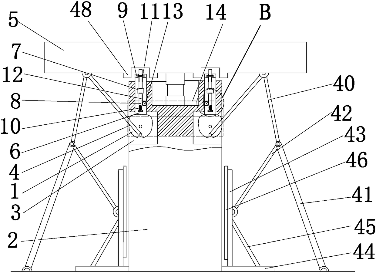
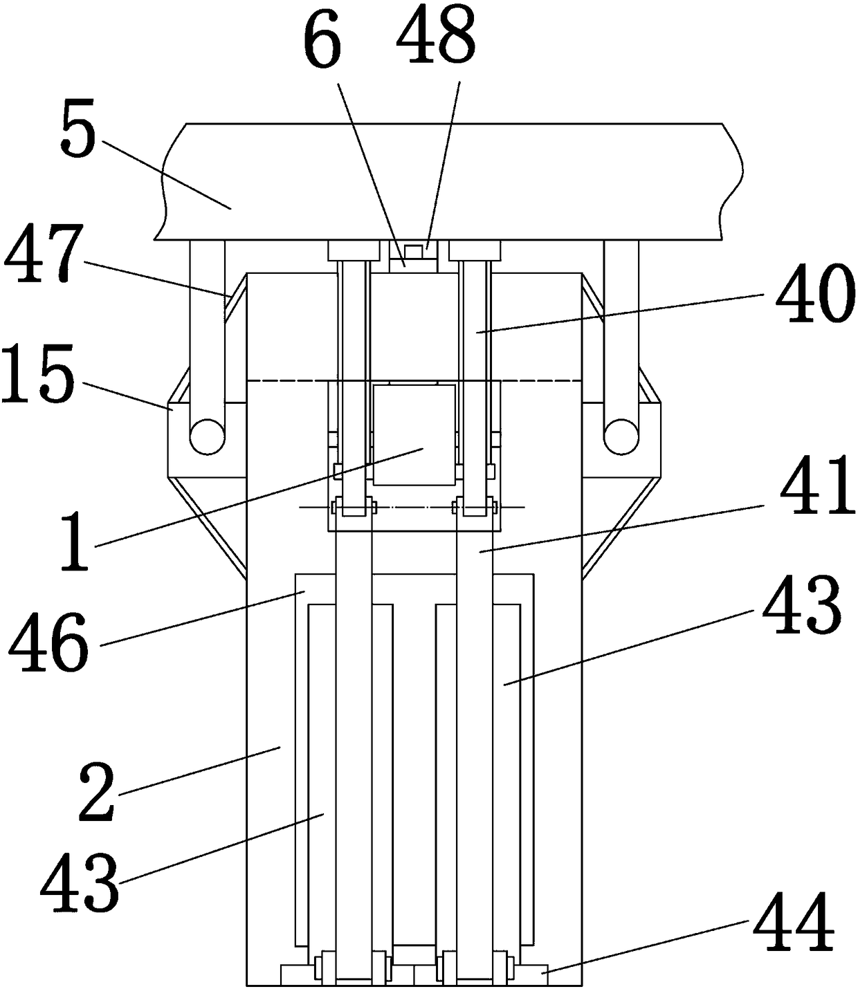
[0029] Embodiment 1, please combine the attached figure 1 , 2, can clearly see the position of the present invention in the bridge, the present invention includes two cams 1, the cams 1 are respectively rotatably connected in the grooves 3 on both sides of the abutment 2, in the initial state, the distance of the cam 1 rotates The farthest point is placed directly below, and the groove 3 where the cam 1 is installed should not be too large, so as not to affect the overall seismic strength of the abutment 2. The lower part of the front end of the cam 1 is rotatably connected with a drive rod 4, and the drive rod 4 is separately One end is tilted outward and hinged below the main beam 5. The horizontal movement of the main beam 5 can drive the cam 1 to rotate through the driving rod 4. The upper part of the groove 3 is connected with the first chute 32 that penetrates the abutment 2 upwards. A retaining rod 6 is placed above the cam 1, and the retaining rod 6 passes through the...

Embodiment 2

[0032] Embodiment 2, on the basis of Embodiment 1, please combine the attached figure 1 , the top of the cam 1 has two symmetrical protrusions along the radial direction of the cam 1 respectively, so that the cam 1 can push up the blocking rod 6 when it rotates clockwise or counterclockwise. The cam 1 is left-right symmetrical, so that the clockwise and counterclockwise motions of the cam give the movement trend of the stop rod to be consistent.

Embodiment 3

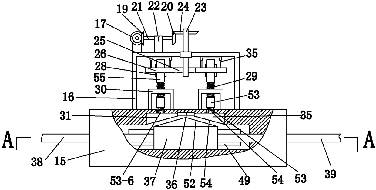
[0033] Example 3, on the basis of Example 1, please combine Figure 5 The telescopic universal joint 18 is that the universal joint 18 includes a second telescopic rod, and the second telescopic rod is slidably connected to the second cylinder 18-4 by the second cylinder 18-4. 4 inside the second movable rod 18-3, the second cylindrical body 18-4 has an axial third chute 18-7 communicating with its inner cavity, and the second movable rod 18-3 is fixed on There is a first sliding block 18-8 axially slidingly fitted in the third chute 18-7, and the free ends of the second movable rod 18-3 and the second cylindrical body 18-4 are respectively fixed with universal joints 18 -2, wherein one universal joint 18-2 is connected on the rotating shaft 18-6, and another universal joint 18-2 is connected on the transmission shaft 18-1. The structure that the third chute 18-7 and the first sliding block 18-8 cooperate with each other is set in the second telescopic rod, so that the second...


PUM


Abstract

The invention relates to a bridge anti-seismic and damping device. The device comprises a first grade anti-seismic and damping structure and a second grade anti-seismic and damping structure, the first grade anti-seismic and damping structure drives a stop lever to move upward through the rotation of a cam, and the cooperation of a top rod and check blocks at the two sides below a cross beam limits the horizontal displacement of the cross beam; the second grade anti-seismic and damping structure drives a first gear to rotate through the vertical displacement of the top rod in the stop lever and then transmits the rotation to a first bevel gear through a telescopic universal coupling, and the first bevel gear is connected with a second grade anti-seismic device to achieve the inclined slopeself-locking of a piston and pressing block to achieve the second grade anti-seismic protection; and the protection of a bridge pier is achieved through a link mechanism under the cross beam. The bridge anti-seismic and damping device has the advantages that the displacement of the bridge cross beam is limited very well, the risk of the beam falling is avoided, the structural seismic damage is reduced, the structural damage degree is reduced, two-stage earthquake protection is achieved, the seismic capability of the bridge itself is greatly improved, the buffering protective capability of thepier can also be strengthened when the earthquake occurs, and the earthquake resistant effect is significant.

Description

technical field [0001] The invention belongs to the technical field of bridge engineering, in particular to a bridge anti-seismic and shock-absorbing device. Background technique [0002] An earthquake is a phenomenon of propagating vibrations that occurs when a part of the earth's interior moves rapidly. When a major earthquake breaks out, it releases huge seismic energy, causing a lot of damage to the surface and man-made engineering, seriously threatening the safety of people's lives and property. The damage to bridges by earthquakes directly affects the smoothness of lifelines in the process of earthquake relief. Therefore, how to improve the seismic capacity of bridges and reduce the damage to bridges caused by earthquakes is a very important issue. [0003] People's travel has gradually developed from walking to transportation, such as cars, trains, airplanes, ships, etc., and a series of roads, railways, etc. When it develops into aerial construction, under such co...

Claims


Application Information

Patent Timeline
IPC IPC(8): E01D19/00
CPCE01D19/00
Inventor 李广慧邓苗毅栗蕾李亮
Owner 西创常州信息技术有限责任公司
Why Eureka
Try Eureka