Eureka AIR delivers breakthrough ideas for toughest innovation challenges, trusted by R&D personnel around the world.

Channel switching device used in fluid pipe and air treatment equipment

A flow channel switching and fluid pipeline technology, applied in pipeline layout, valve devices, mechanical equipment, etc., can solve the problems that the filter cannot effectively limit the outlet wind speed, hidden dangers, and low air dust removal efficiency

Active Publication Date: 2018-08-28
GUANGDONG MIDEA WHITE GOODS TECH INNOVATION CENT CO LTD +1
View PDF5 Cites 4 Cited by
  • Summary
  • Abstract
  • Description
  • Claims
  • Application Information

AI Technical Summary

Problems solved by technology

For wall-mounted and cabinet-type fresh air fans, although the ventilation ducts are saved to a certain extent, they occupy a large space, the machine is heavy, and its power is also large, and the energy consumption is too high, so it is very uneconomical to use.
Through-the-wall fresh air fans are generally filtered through a filter. The efficiency of one-time filtration is low, and it is difficult to meet the requirements of fresh air. Moreover, because they need to be installed in a wall hole as a whole, the diameter of the wall hole is too high, and the practicability is reduced, which seriously affects consumption. the choice of
[0007] In addition, in addition to the above-mentioned central fresh air system, wall-mounted and cabinet-type fresh air fans, in addition to using filters as air dust removal devices, some of them also use electrostatic precipitators as air dust removal devices, but these electrostatic precipitators are limited to the inherent characteristics of electrostatic fields. Mode, which uses traditional parallel and spaced opposite plates to form an electrostatic field, resulting in the bulky size of these fresh air fans, taking up too much space, and the air flow to be dusted passes straight and fast, often resulting in low air dust removal efficiency, introducing The quality of fresh air is often poor, which affects human health, which leads to the low acceptance of fresh air fans using these electrostatic precipitators in the market
In addition, fresh air fans using electrostatic precipitators also have some hidden hazards that affect human health and are difficult for people in the field to discover for a long time, resulting in relatively large safety hazards for these fresh air fans
[0008] What's more serious is that the above-mentioned types of fresh air fans generally have the defect of single function, and only have the function of external air circulation. damaged, and the quality of the air drawn in and filtered from the outside is not even as good as the air inside
In view of this, there are also some relatively rough fresh air fans with internal circulation function in the prior art. For example, some fresh air fans use two fans to form internal circulation mode and external circulation mode relatively independently in order to form an internal circulation working mode. , this not only fails to overcome the above-mentioned existing defects of the existing fresh air blower, but also leads to a larger volume of the fresh air blower, a more complex structure, and more complicated air duct laying
In addition, there are some wall-mounted and cabinet-type fresh air fans that directly open an indoor air inlet on the indoor body, and selectively block the indoor air inlet or the external air inlet connected to the external air inlet pipe through the switching cover inside the body to Realize the switching between the external circulation working mode and the internal circulation working mode. However, this structural form does not change the essence of the wall-mounted and cabinet-type fresh air fans. What's more serious is that this rough method of directly opening indoor air inlets on the indoor body of wall-mounted and cabinet-type fresh air fans will cause serious defects such as roaring, filter damage, and dead air circulation.
Specifically, since the air intake cavity of the indoor main unit of the wall-mounted and cabinet-type fresh air fans is generally large, the indoor air inlet is directly opened on the indoor main unit, and the distance between the indoor air inlet and the fan is relatively short, and the indoor air drawn by the fan is Unlike the external air intake that can be buffered through the external air intake duct, it directly enters the air intake cavity of the indoor main unit at high speed, causing the indoor body to tremble and even roar. filter element, the filter element is easily damaged and cannot perform a good filtering effect
Once the filter element is damaged, the filter element cannot effectively limit the outlet wind speed, and the flow velocity of the air inlet and outlet tends to be close to each other. The inspection proves that at this time, it is very easy to form a dead cycle of indoor air in a local area around the indoor main unit. , that is, at this time, the internal circulation working mode of the wall-mounted and cabinet-type fresh air fans is basically unable to effectively purify the indoor air, and is in an invalid state
[0009] The above-mentioned defects of the fresh air machine have formed a technical bottleneck restricting the further development of the fresh air machine. Those skilled in the art have not realized that there are serious hidden dangers in some harmful factors, especially how to make the fresh air machine work on the basis of both internal and external circulation modes. , effectively saves indoor space, and has good and reliable working performance, which has become a technical problem in this field

Method used


Image

  • Channel switching device used in fluid pipe and air treatment equipment
  • Channel switching device used in fluid pipe and air treatment equipment
  • Channel switching device used in fluid pipe and air treatment equipment

Examples


Embodiment Construction

[0077] Specific embodiments of the present invention will be described in detail below in conjunction with the accompanying drawings. It should be understood that the specific embodiments described here are only used to illustrate and explain the present invention, and are not intended to limit the present invention.

[0078] In the present invention, unless stated to the contrary, the used orientation words such as "up, down, top, bottom" generally refer to the directions shown in the drawings or refer to the vertical, perpendicular or gravitational directions The terms used to describe the mutual positional relationship of the various components mentioned above. "Inner and outer" refer to the inner and outer sides of a lumen, an inner cavity, or indoors and outdoors.

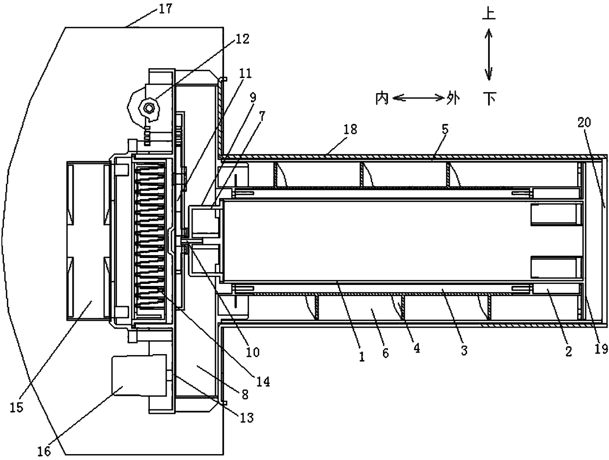
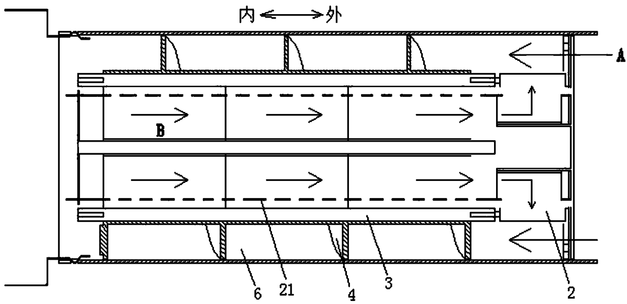
[0079] Such as Figure 8 , Figure 9 As shown, the present invention firstly provides a flow channel switching device used in fluid pipelines, including:

[0080] Inner tube 1, see Figure 8 , the inner t...


PUM


Abstract

The invention discloses a channel switching device used in a fluid pipe and air treatment equipment. The channel switching device comprises an inner pipe (1), an annular pipe chamber (6) is formed between the inner pipe and the fluid pipe, the fluid inlet end of the inner pipe is connected with an inner pipe end surface disc, the central blocking disc part (1b) blocks the fluid inlet of the innerpipe, the outer ring part of the inner pipe end surface disc covers the end surface at the fluid inlet end of the annular pipe chamber and is provided with a first annular chamber opening (1c) which is communicated with the annular pipe chamber, the pipe body outer wall at the fluid inlet end of the inner pipe is provided with a first communicating opening (1d) which is communicated with the annular pipe chamber; and a switching blocking sleeve (2) which comprises a sleeve part (2a) and a blocking sleeve end surface disc (2b), wherein the blocking sleeve end surface disc is provided with a central through hole, and the outer peripheral part of the blocking sleeve end surface disc is provided with a second annular chamber opening (2c). The outer peripheral wall of the sleeve part is provided with a second communicating opening (2d). The channel switching device has advantages of simple structure, effective realization of channel switching control in a narrow channel space, and easy accurate control of a rotating mode.

Description

technical field [0001] The present invention relates to air treatment equipment, in particular to a channel switching device used in a fluid pipeline, and furthermore, the present invention also relates to an air treatment equipment. Background technique [0002] The problem of air pollution has become more and more prominent in today's society, seriously endangering people's health. In order to deal with the worsening air pollution problem, various air treatment equipment are widely used in homes, office buildings, hospitals, schools, etc., among which the fresh air device It is a kind of air treatment equipment with wide application and strong practicability. At present, the products in the fresh air industry are mainly central fresh air systems. In addition, wall-mounted, cabinet-type fresh air fans, and through-wall fresh air fans are also widely used. [0003] The central fresh air system includes a main unit installed on the top of the room, an air inlet pipe and an a...

Claims


Application Information

Patent Timeline
IPC IPC(8): F16K11/02B03C3/40F24F13/02
CPCB03C3/40B03C2201/04F16K11/02F24F13/02
Inventor 大森宏王文鹏岳宝
Owner GUANGDONG MIDEA WHITE GOODS TECH INNOVATION CENT CO LTD
Why Eureka
Eureka Blog
Learn More