Self-heating floor and self-heating floor system thereof

A self-heating and flooring technology, which is applied in the direction of electric heating system, heating system, household heating, etc., can solve the problems of uneven ground, non-heating of the floor, and inability to lay in large areas, so as to achieve paving operations suitable for large areas , Improve the effect of paving efficiency

Pending Publication Date: 2018-08-28
无锡中暖科技有限公司
View PDF1 Cites 5 Cited by
  • Summary
  • Abstract
  • Description
  • Claims
  • Application Information

AI Technical Summary

Problems solved by technology

[0004] The applicant noticed that the prior art had the technical problem of being unable to lay large areas, and the defects of being unable to realize modular production and flexible assembly; in particular, there was no disclosure of how to electrically connect multiple heating elements. Any technical presentation of heating elements for heating floors
Although there are electrical connectors with male and female terminals in the prior art, in the actual use environment of the floor, due to the inevitable deformation of the floor and the unevenness of the original ground, the wires connecting the male and female terminals may be broken. Dangerous, resulting in a lack of heat on the floor or a series of safety issues such as fires

Method used


Image

  • Self-heating floor and self-heating floor system thereof
  • Self-heating floor and self-heating floor system thereof
  • Self-heating floor and self-heating floor system thereof

Examples


Embodiment 1

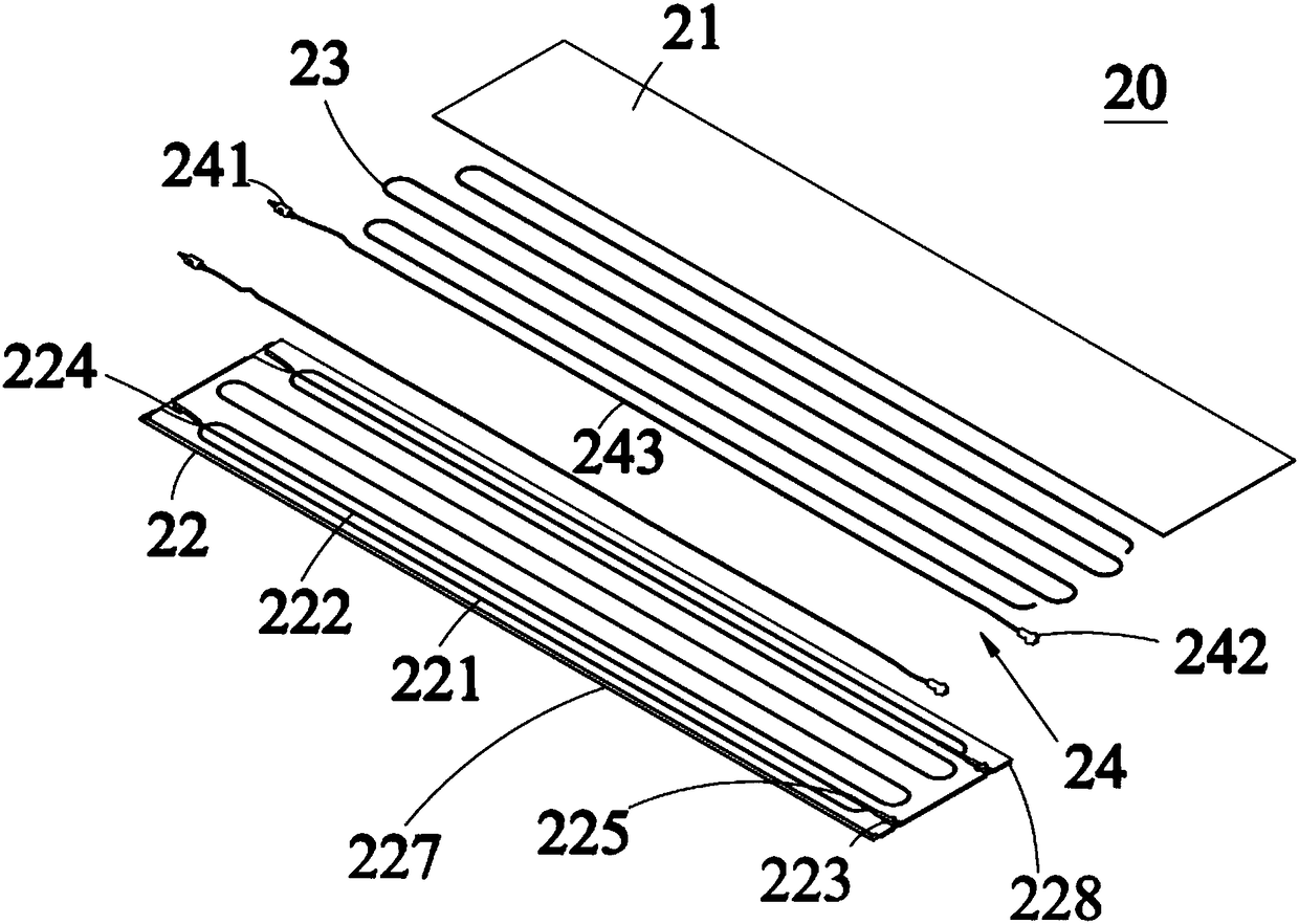
[0043] ginseng figure 2As shown, this embodiment discloses a self-heating floor 20, including: a bottom plate 22 and a top plate 21 that are laminated and bonded, a heating cable 23 coiled between the bottom plate 22 and the top plate 21, and an even number of electrically connected heating elements. Electrical connector 24 for cable 23 . Specifically, the bottom plate 22 and the top plate 21 are made of PVC, wood plastic, stone plastic or solid wood. In this implementation, the bottom plate 22 is made of PVC, and the top plate 21 is made of solid wood.

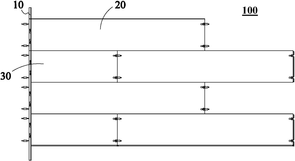
[0044] Specifically, in this embodiment, the diameter of the heating cable 23 can be 1-6mm, and the heating power is set at 150-350W / M 2 . A plurality of heating cables 23 can be connected in parallel through an electrical connector 24, and a plurality of heating cables 23 in two adjacent rows of self-generating heating floors 20 can be connected in parallel through an electrical connector 24, and simultaneously connected...

Embodiment 2

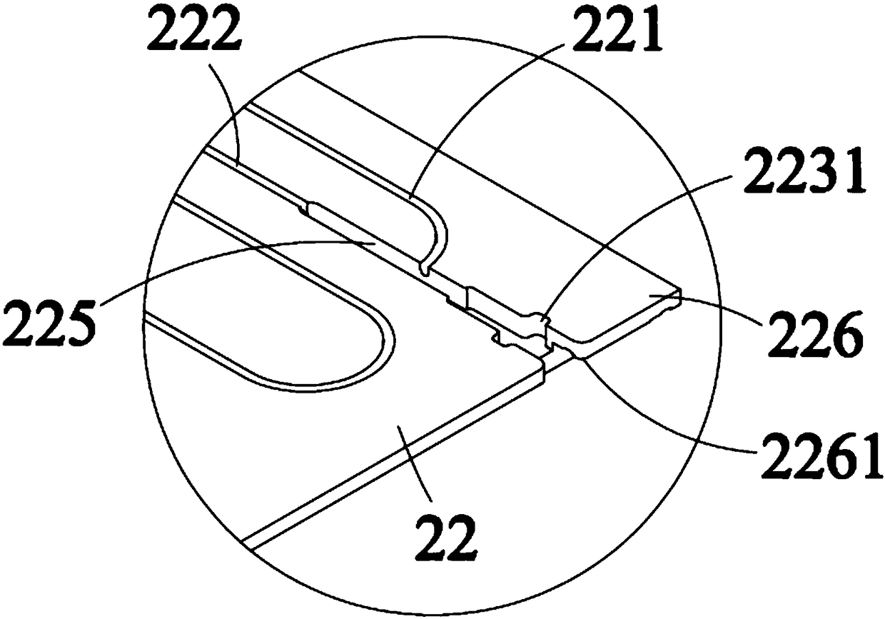
[0062] This embodiment shows a first modified example of a self-heating floor 20. Compared with Embodiment 1, the main difference is that, in this embodiment, the surface of the bottom plate 22 facing the top plate 21 forms a completely accommodating heating cable 23 The first receiving groove 221 of the electrical connector 24 and the second receiving groove 222 that completely accommodate the electrical connector 24, and the two ends of the second receiving groove 222 respectively form a first expansion that completely accommodates the terminals at the two ends of the electrical connector 24. The recessed portion 224 and the second expanded recessed portion 223 . Wherein, the female terminal 242 is completely accommodated in the second expanded concave portion 223 , the male terminal 241 is completely accommodated in the first expanded concave portion 224 , and the upper plane 2424 of the female terminal 242 is flush with the upper surface of the bottom plate 20 At the same ...

Embodiment 3

[0065] This embodiment shows a second modification of the self-heating floor 20. Compared with Embodiment 1 and / or Embodiment 2, especially compared with Embodiment 2, the main difference is that in the embodiment The first receiving groove 221 and the second receiving groove 222 mentioned above are all formed on the bottom surface of the top plate 21, and the upper surface of the bottom plate 22 may not be provided with the first receiving groove 221 and the second receiving groove 222, so as to form a smooth surface.

[0066] For the technical solutions in this embodiment that are the same as those in Embodiment 1 and / or Embodiment 2, please refer to Embodiment 1, and details will not be repeated here.


PUM

PropertyMeasurementUnit
Diameteraaaaaaaaaa
Heating poweraaaaaaaaaa
Thicknessaaaaaaaaaa

Abstract

The invention discloses a self-heating floor and a self-heating floor system thereof. The self-heating floor comprises a bottom plate, a top plate, heating cables and an even umber of electric connectors, wherein the bottom plate and the top plate are overlapped and adhered; the heating cables are arranged between the bottom plate and the top plate in a coiling manner; the electric connectors areelectrically connected to the heating cables, and each electric connector comprises a male terminal, a female terminal, and an electric cable for connecting each male terminal and the corresponding female terminal; first storing grooves and second storing grooves are formed in the surface, facing the top plate, of the bottom plate; at least part of each first storing groove is used for storing thecorresponding heating cable, and at least part of each second storing groove is used for storing the corresponding electric connector; first expanding concaving parts and second expanding concaving parts are correspondingly formed at two ends of the second storing grooves; at least part of each first expanding concaving part and at least part of each second expanding concaving part are used for storing terminals at two end parts of the electric connectors. According to the self-heating floor, the modular production and assembling can be realized, so that the paving efficiency is improved; andmoreover, the defects of unstable quality, entering of water vapor and high potential risk caused by separating of the male and female terminals due to the deformation under force in the use processcan be avoided.

Description

technical field [0001] The invention relates to the technical field of floor with self-heating function, in particular to a self-heating floor and a self-heating floor system formed by laying the self-heating floor. Background technique [0002] In the home system, floors with heating function are being enthusiastically sought after. The heating floor usually adopts two heating methods. The first is the hot water circulation method: it uses a gas water heater to heat the water, and passes through the densely distributed water pipes laid under the floor, and continuously circulates the heating to heat the floor. Finally, the heat is radiated into the room to play a heating effect. The second is to use electric heating to generate heat, and specifically, use commercial power as the energy source, lay electric heating elements (such as carbon fiber heating plates, heating cables) inside the floor, and use the heat generated by the electric heating elements Heat the room. [...

Claims


Application Information

Patent Timeline
IPC IPC(8): F24D13/02F24D19/00E04F15/02E04F19/04
CPCF24D13/024F24D19/00E04F15/02E04F19/04E04F19/0481E04F2019/044E04F2290/023
Inventor 夏东升湛模规王仁祥李宏英
Owner 无锡中暖科技有限公司
Why Eureka
Try Eureka