
An Ultrasonic Thickness Gauge with Marking Function for Small Pipes

A marking function, ultrasonic technology, applied in the direction of using ultrasonic/sonic/infrasonic waves, instruments, measuring devices, etc., can solve the problems of labeling the position of the label pen, difficult for testing personnel to accurately locate, and prone to deviation in measurement results, to improve measurement accuracy. , Easy and fast loading and unloading, and the effect of improving practicability

Active Publication Date: 2020-06-05
东营市鑫海石油装备有限公司
View PDF9 Cites 0 Cited by
  • Summary
  • Abstract
  • Description
  • Claims
  • Application Information

AI Technical Summary

Problems solved by technology

[0003] In the actual measurement process of the existing ultrasonic thickness gauge, in order to ensure the accuracy of the measurement, the probe needs to maintain a vertical angle with the workpiece to be measured. Vertical, which leads to deviations in the measurement results. Not only that, in the process of measuring the pipeline, some parts need to be marked, but because the inspector usually holds the probe and the measuring device with both hands during the measurement, it is impossible to mark the position with a label pen. After the probe is removed, it is difficult for the inspectors to locate accurately, which makes it difficult for the existing ultrasonic thickness gauge to be suitable for the detection and marking of small pipelines

Method used


Image

  • An Ultrasonic Thickness Gauge with Marking Function for Small Pipes
  • An Ultrasonic Thickness Gauge with Marking Function for Small Pipes
  • An Ultrasonic Thickness Gauge with Marking Function for Small Pipes

Examples


Embodiment Construction

[0026] The present invention is described in further detail now in conjunction with accompanying drawing. These drawings are all simplified schematic diagrams, which only illustrate the basic structure of the present invention in a schematic manner, so they only show the configurations related to the present invention.

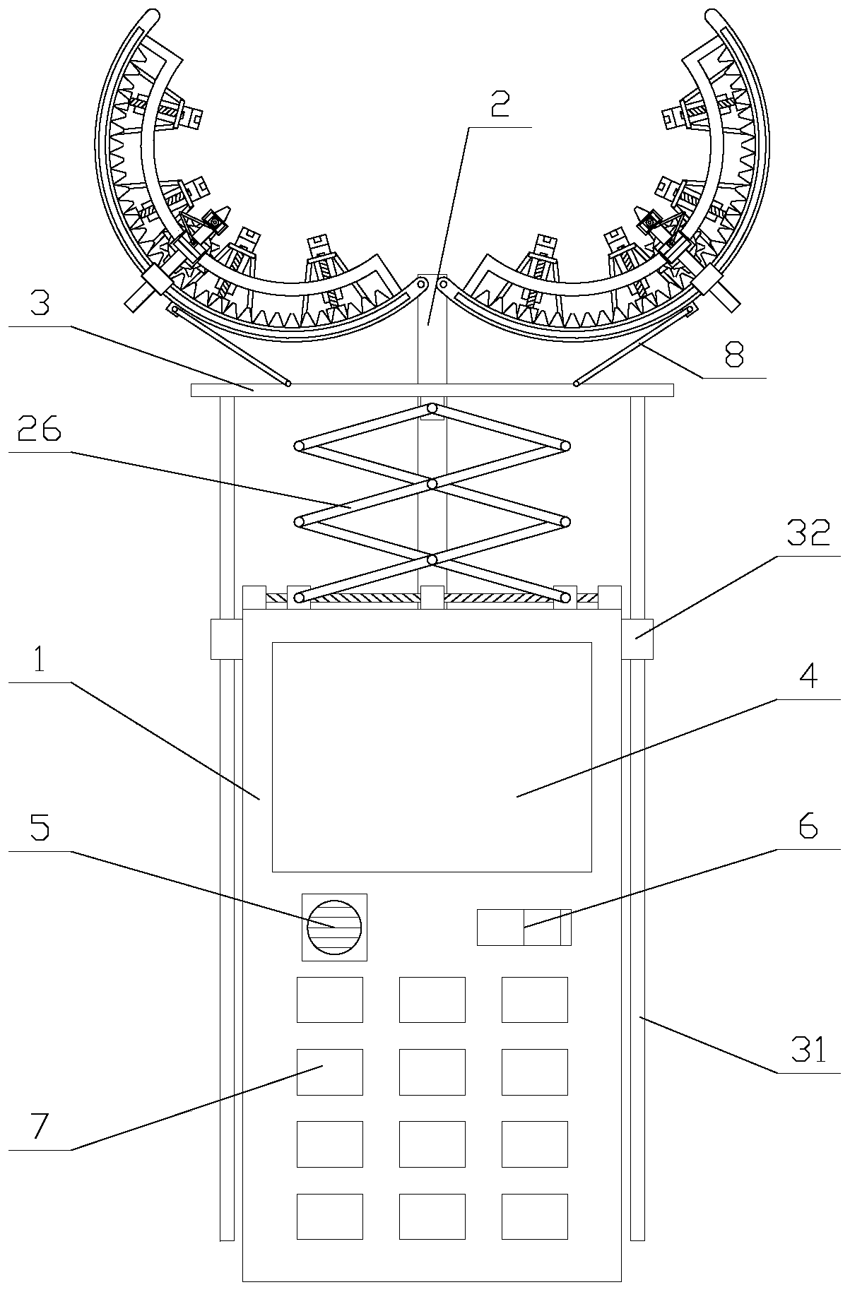
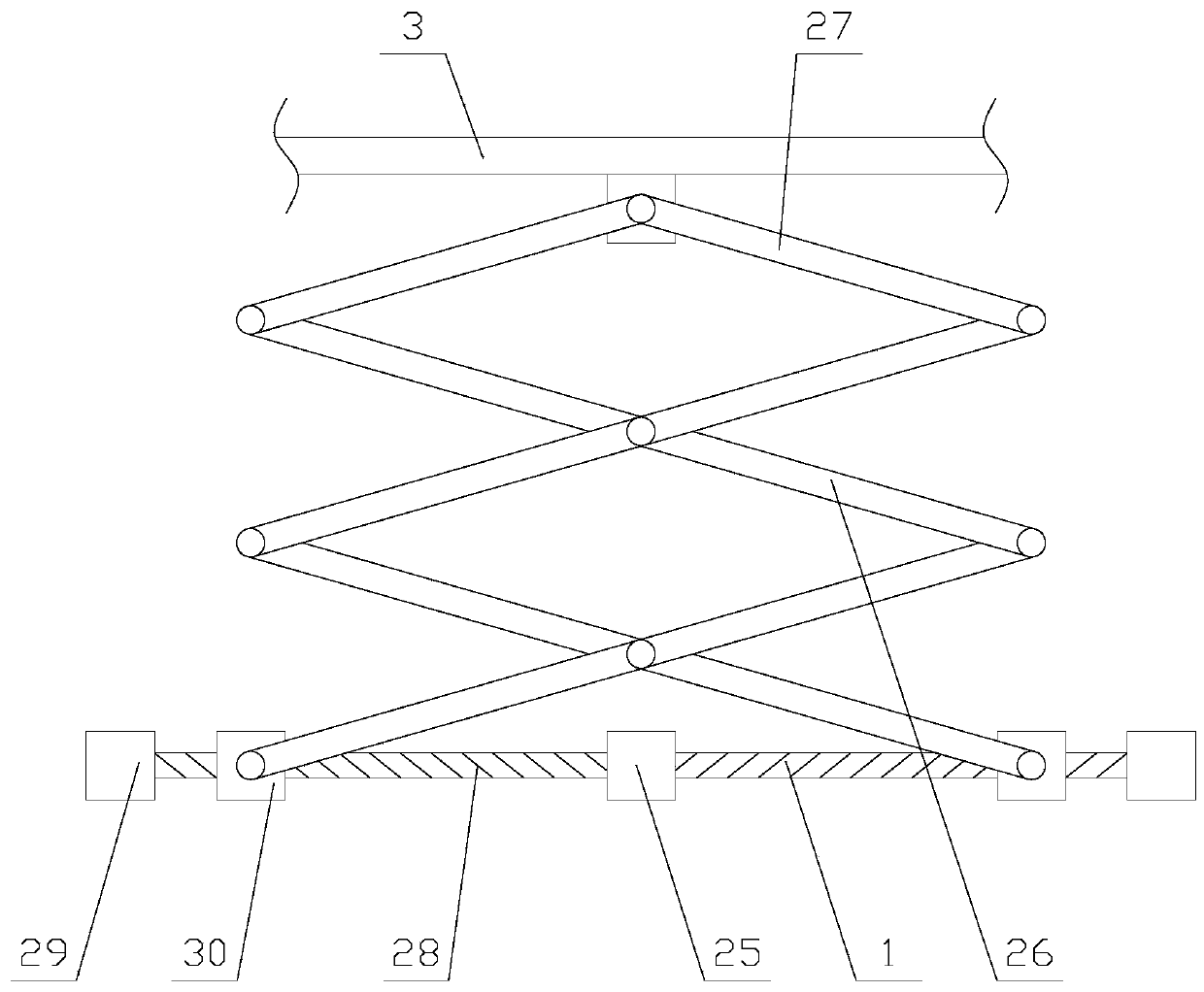
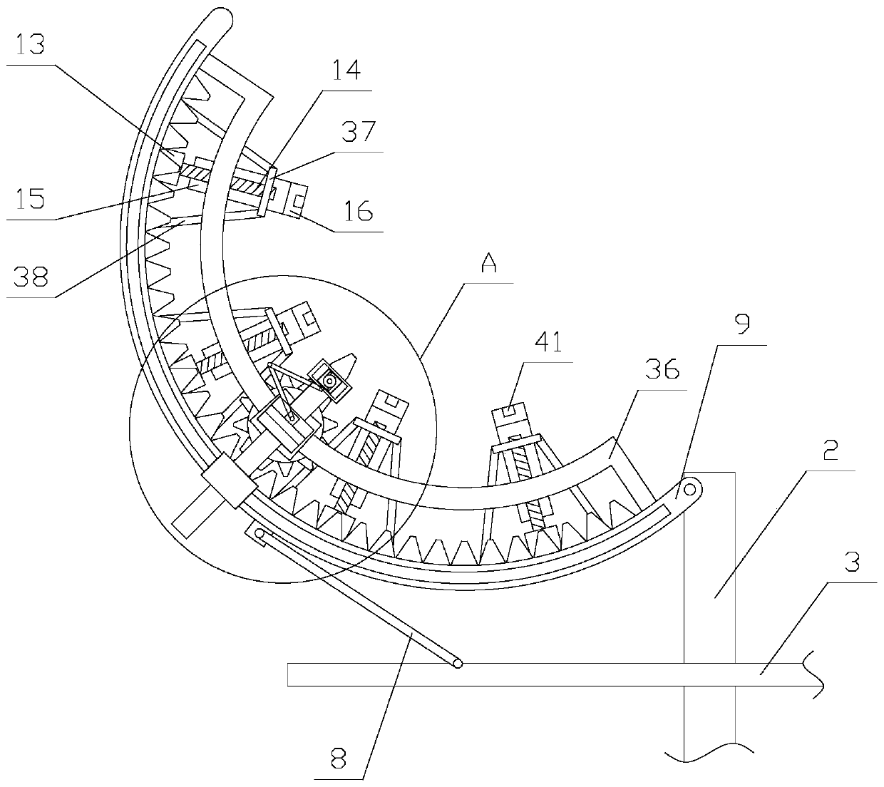
[0027] Such as figure 1 As shown, an ultrasonic thickness gauge with marking function suitable for small pipelines includes a main body 1, a telescopic mechanism, a sliding rod 2, a movable plate 3 and two detection mechanisms, and one end of the sliding rod 2 is fixed on the main body 1 Above, the two detection mechanisms are respectively located on both sides of the other end of the slide bar 2, the movable plate 3 is sleeved on the slide bar 2, the telescopic mechanism is located between the movable plate 3 and the main body 1, and the telescopic mechanism is connected to the main body 1. The movable plate 3 is connected by transmission, and the main body ...


PUM


Abstract

The invention relates to an ultrasonic thickness gauge having the marking function and being suitable for small pipelines. The ultrasonic thickness gauge comprises a body, a telescoping mechanism, a sliding rod, a moving board and two detection mechanisms, wherein the detection mechanisms comprise struts, curved boards, rotating assemblies, rotating boards, support boards, probes, label assembliesand multiple fastening assemblies, the fastening assemblies comprise multiple fastening units, the fastening units comprise first motors, first driving shafts, sleeves and fastening blocks, and the label assemblies comprises first rings, second rings, air pumps, air bags, second motors, first connection rods, second connection rods and label pens. The ultrasonic thickness gauge is advantaged in that pipelines are fixed through fixing assemblies, the probes are made to measure in a vertical angle, measurement precision is improved, moreover, the label pens are made to move at the desired position through the label assemblies for labeling, a detector is convenient to master the pipeline situations, and device practicality is improved.

Description

technical field [0001] The invention relates to the field of ultrasonic thickness measuring equipment, in particular to an ultrasonic thickness measuring instrument with a marking function suitable for small pipelines. Background technique [0002] The ultrasonic thickness gauge measures the thickness according to the principle of ultrasonic pulse reflection. When the ultrasonic pulse emitted by the probe passes through the object to be measured and reaches the interface of the material, the pulse is reflected back to the probe, which is determined by accurately measuring the time of ultrasonic propagation in the material The thickness of the material to be tested can be measured by this distance for all kinds of materials that can make ultrasonic waves propagate inside them at a constant speed. [0003] In the actual measurement process of the existing ultrasonic thickness gauge, in order to ensure the accuracy of the measurement, the probe needs to maintain a vertical angl...

Claims


Application Information

Patent Timeline
Patent Type & Authority Patents(China)
IPC IPC(8): G01B17/02
CPCG01B17/02
Inventor 李健蒙泽喜
Owner 东营市鑫海石油装备有限公司
Learn More