Disturbance simulation method of instrument landing system

An instrument landing system and simulation method technology, applied in design optimization/simulation, instrumentation, calculation, etc., can solve the problem of inaccurate simulation data, and achieve the effect of reducing data transmission, reducing bandwidth pressure, and reducing complexity

Active Publication Date: 2018-08-28
中国民用航空中南地区空中交通管理局
View PDF7 Cites 6 Cited by
  • Summary
  • Abstract
  • Description
  • Claims
  • Application Information

AI Technical Summary

Problems solved by technology

Although the ray tracing method can perform efficient approximate calculations on DDM, since the electric wave is equivalent to a ray beam during the ca

Method used


Image

  • Disturbance simulation method of instrument landing system
  • Disturbance simulation method of instrument landing system
  • Disturbance simulation method of instrument landing system

Examples


Embodiment 1

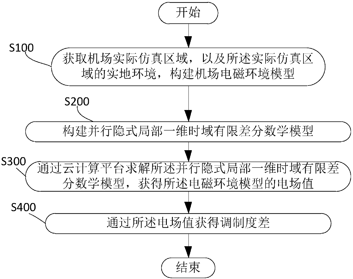
[0085] Such as figure 1 As shown, an ILS disturbance simulation method provided by an embodiment of the present invention includes the following steps:

[0086] Step S100: Obtain the actual simulation area of ​​the airport and the actual environment of the actual simulation area, and construct an airport electromagnetic environment model;

[0087] Step S200: constructing a parallel implicit local one-dimensional time-domain finite-difference mathematical model;

[0088] Step S300: solving the parallel implicit local one-dimensional finite-difference time-domain mathematical model through the cloud computing platform to obtain the electric field value of the electromagnetic environment model;

[0089] Step S400: Obtain a modulation difference through the electric field value.

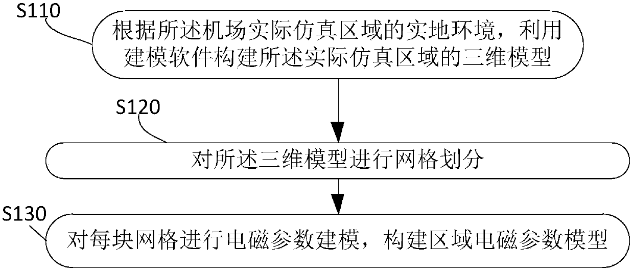
[0090] Step S100 obtains the actual simulation area of ​​the airport, and the actual environment of the actual simulation area, and constructs the electromagnetic environment model of the airport, spec...

Embodiment 2

[0153] Embodiment 2 of the present invention also provides a computer-readable storage medium, wherein a computer program is stored in the computer-readable storage medium, wherein the above-mentioned ILS disturbance simulation method can be realized when the computer program is running.

Embodiment 3

[0155] Embodiment 3 of the present invention also provides an electronic device, including a memory, a processor, and a computer program stored in the memory and operable on the processor. When the processor executes the program, the above-mentioned ILS disturbance simulation method is implemented.

[0156] The instrument landing system disturbance simulation method, computer-readable storage medium and electronic equipment provided by the embodiments of the present invention have the following significant beneficial effects:

[0157] 1) The tri-diagonal matrix is ​​decomposed by the Sherman-Morrison method, which improves the distributed solution efficiency of the LOD-FDTD algorithm;

[0158] 2) Only r, H, and t three sets of data are being transmitted between nodes, which can greatly reduce the bandwidth pressure of the cloud platform;

[0159] 3) When the CFLN increases, compared with the existing algorithms, this algorithm has the characteristics that the results are not e...


PUM


Abstract

The invention discloses a disturbance simulation method of an instrument landing system. The method comprises the following steps: S100, acquiring an actual simulation region of an airport and the site environment of the actual simulation region so as to construct an electromagnetic environment model of the airport; S200, constructing a parallel implicit local one-dimensional time domain finite difference mathematical model; S300, solving the parallel implicit local one-dimensional time domain finite difference mathematical model through a cloud computing platform to obtain the electric fieldvalue of the electromagnetic environment model; and S400, obtaining the difference in degree of modulation according to the electric field value. The disturbance simulation method of the instrument landing system, disclosed by the invention, lowers the complexity of computation, reduces the data transmission among nodes and reduces the bandwidth pressure, so that the instrument landing system canbe normally used on a cloud platform.

Description

technical field [0001] The invention relates to the field of civil aviation equipment, in particular to an instrument landing system disturbance simulation method. Background technique [0002] With the development of the aviation industry, the number of global flights is gradually increasing, and the impact of bad weather on the punctuality of flights is becoming more and more serious. The instrument landing system has attracted more and more attention from air traffic control. Instrument Landing System (ILS, also translated as instrument landing system, blind landing system), is the most widely used aircraft precision approach and landing guidance system. Its function is to realize the localizer and glideslope guidance by two beams of radio signals emitted from the ground, and establish a virtual path pointing from the runway to the air. The aircraft determines its relative position with the path through the onboard receiving equipment, so that the aircraft can move along ...

Claims


Application Information

Patent Timeline
IPC IPC(8): G06F17/50G06T17/00
CPCG06T17/00G06F30/20
Inventor 陆永东王明甲谭峻东龙云亮黎子豪
Owner 中国民用航空中南地区空中交通管理局
Why Eureka
Try Eureka