Gray level and binary image expansion corrosion processing method based on FPGA

A binary image and corrosion processing technology, applied in the field of image processing, can solve problems such as performance limited memory bandwidth, and achieve the effect of reducing the number of visits and speeding up computing

Active Publication Date: 2018-08-28
HEFEI CHIP FOUND MICROELECTRONICS EQUIP CO LTD
View PDF3 Cites 3 Cited by
  • Summary
  • Abstract
  • Description
  • Claims
  • Application Information

AI Technical Summary

Problems solved by technology

In the existing technology, expansion and erosion need to read the target element covered by the structural element multiple times, and the performance is limited by the memory bandwidth.

Method used


Image

  • Gray level and binary image expansion corrosion processing method based on FPGA
  • Gray level and binary image expansion corrosion processing method based on FPGA
  • Gray level and binary image expansion corrosion processing method based on FPGA

Examples


Embodiment 1

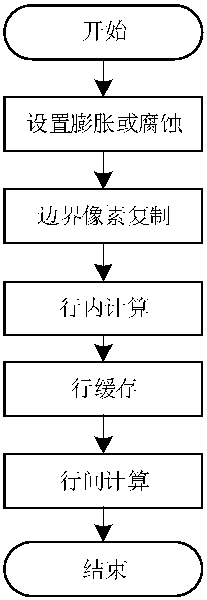
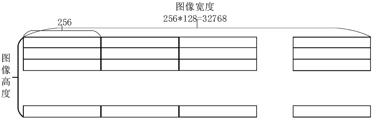
[0033] Select the grayscale image with a structural element window size of 3×3, a grayscale of 2, and a width of 32768 as the first embodiment, such as figure 1 , figure 2 , image 3 , Figure 4 , Figure 5 , Figure 6 and Figure 7 As shown, the process steps are described as follows:

[0034] Step 1: Set dilation or erosion, and determine the calculation method, which is used to specify the intra-row calculation and inter-row calculation methods.

[0035] Step 2: Copy the boundary pixels according to the window size of the structural element. The size of the structural window is 3×3, so the number of copied boundary pixels is 1; the boundary copy is realized by buffering the 2-shot register cache. The schematic diagram of the boundary copy is as follows Figure 4 shown. When copying border pixels, the first and last border pixels copy their own border pixels, and the middle border pixels copy adjacent border pixels.

[0036] Step 3: Perform in-line calculation on th...

Embodiment 2

[0040] Select the binary image with a structural element window size of 3×3 and a width of 32768 as the second embodiment, such as figure 1 , figure 2 , image 3 , Figure 8 , Figure 9 and Figure 10 As shown, the process steps are described as follows:

[0041] Step 1: Set dilation or erosion, and determine the calculation method, which is used to specify the intra-row calculation and inter-row calculation methods.

[0042] Step 2: Copy the boundary pixels according to the structuring element window size. Embodiment 2 The size of the structural window is 3×3, so the number of copied boundary pixels is 1. Embodiment 2 Realize boundary copy by caching 2 beat register cache, the schematic diagram of boundary copy is as follows Figure 8 shown. When copying border pixels, the first and last border pixels copy their own border pixels, and the middle border pixels copy adjacent border pixels.

[0043] Step 3: Perform in-row calculation on the data after copying the bound...

Embodiment 1

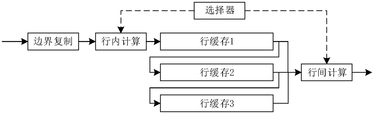
[0046] Embodiment 1 and Embodiment 2 have the same implementation block diagram. The implementation block diagram adopts a pipeline structure, and the data enters the boundary copy, intra-row calculation, row cache and inter-row calculation unit components in turn, and the selector controls the intra-row calculation and inter-row calculation units respectively. The size of the structural element window is optional, and the present invention takes the window size of 3*3 as an example for illustration, which can be reflected in figure 2 The number of middle row caches is 3, Figure 6 The number of instantiated RAM is 3, Figure 4 and Figure 8 The number of border pixels assigned in the middle is 1, that is (3-1) / 2, Figure 5 , Figure 7 , Figure 9 and Figure 10 3 pixels are used as the calculation unit, but the structural element window is not drawn separately.

[0047] In summary, the present invention duplicates the left and right borders, and the width of the image...


PUM


Abstract

The invention relates to a gray level and binary image expansion corrosion processing method based on an FPGA. The method comprises the following sequential steps of setting expansion or corrosion, and determining a calculation mode; conducting the left boundary pixel and the right boundary pixel copying according to the width of the structural element window; performing intra-line calculation onthe data copied from the left and right boundary pixels according to an expansion corrosion algorithm; using the RAM of the FPGA for achieving the calculation result in the cache line of one shift register; reading data in the cache RAM when the calculation result in the cache line reaches the height of one structural element window, and outputting the data after the cache data lines are calculated again according to the expansion corrosion algorithm. The invention is advantageous in that the width of the image is consistent with the width of an original image after the left boundary and the right boundary are copied, and the width of the image after expansion and corrosion is consistent with the width of the original image; through a line cache and an assembly line, the number of times ofaccess of a target element covered by the structural element window is effectively reduced, and the acceleration calculation of expansion and corrosion is realized.

Description

technical field [0001] The invention relates to the technical field of image processing, in particular to an FPGA-based dilation and erosion processing method for grayscale and binary images. Background technique [0002] Based on set theory, mathematical morphology defines a set of transformations based on the set of structural elements. It calculates the transformation of target elements and structural elements to obtain the shape of the object, so as to achieve the purpose of image analysis and recognition. [0003] Dilation and erosion are fundamental transformations in mathematical morphology, defined as the union and intersection of a structure element and a target element, respectively. For binary images, that is, images with pixel values ​​of 0 and 1, expansion and erosion correspond to the OR operation and AND operation of the structure element covering the target element; for grayscale images, that is, the pixel values ​​​​are finite non-negative integers, expans...

Claims


Application Information

Patent Timeline
Patent Type & Authority Applications(China)
IPC IPC(8): G06T7/155G06T1/60
CPCG06T1/60G06T7/155
Inventor 卞洪飞
Owner HEFEI CHIP FOUND MICROELECTRONICS EQUIP CO LTD
Why Eureka
Try Eureka