Textile knitting wool dyeing and drying equipment

A technology for drying equipment and wool, which is applied in the processing of textile material equipment configuration, textile and papermaking, and textile material processing.

Active Publication Date: 2018-08-31
ZHANGJIAGANG YANGZI DYEING & FINISHING CO LTD
View PDF4 Cites 10 Cited by
  • Summary
  • Abstract
  • Description
  • Claims
  • Application Information

AI Technical Summary

Problems solved by technology

[0006] In order to overcome the disadvantages that the dyes precipitate during the dyeing process, which will affect the quality of the dyeing, and the wool cannot be dried in time during the dyeing process, causing the wool to stick, the technical problem to be solved by the present invention is to provide a A wool dyeing and drying equipment for textiles that stirs the dye so that no precipitation occurs and does not affect the quality of the dyeing, and can dry the wool in time during the dyeing process

Method used


Image

  • Textile knitting wool dyeing and drying equipment
  • Textile knitting wool dyeing and drying equipment
  • Textile knitting wool dyeing and drying equipment

Examples


Embodiment 1

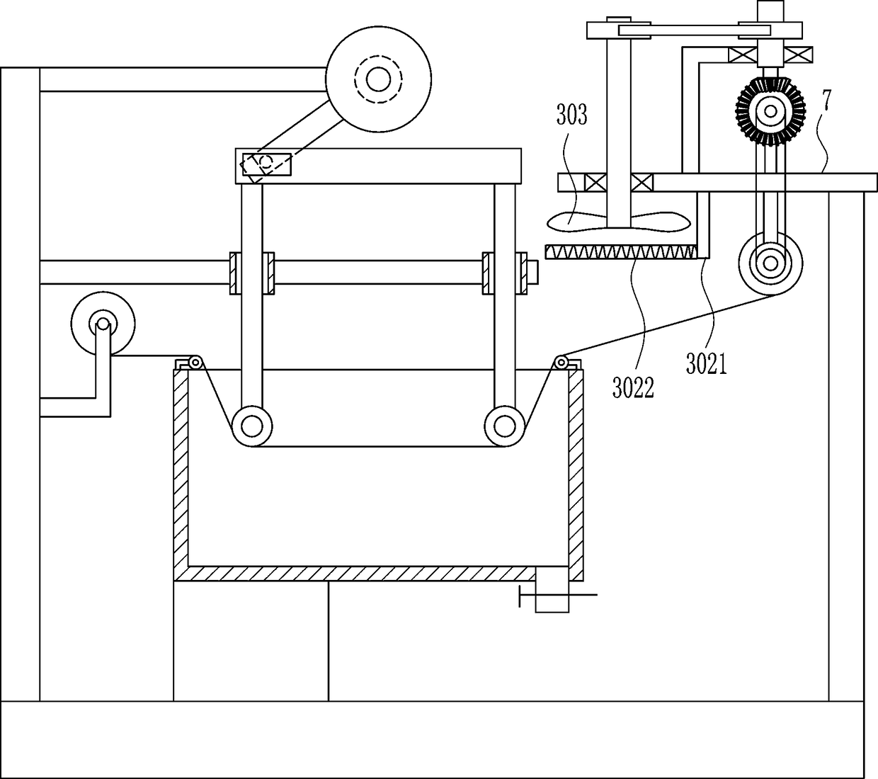
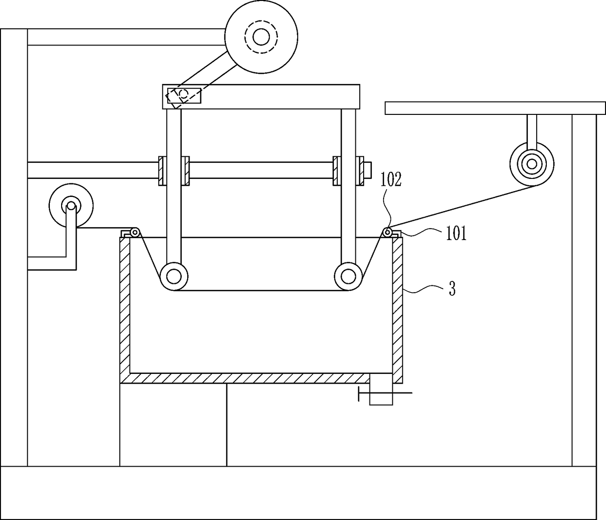
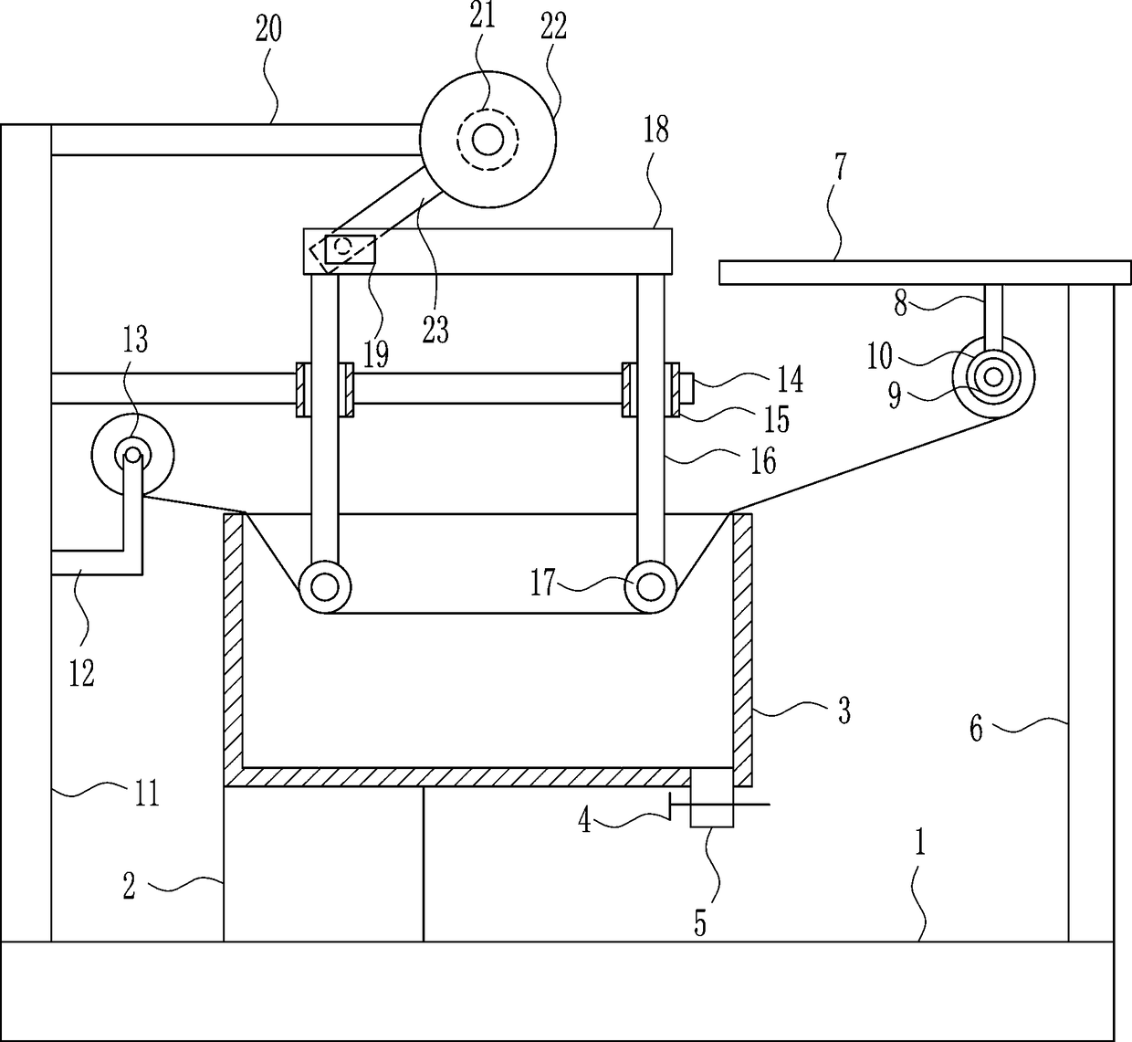
[0028] A kind of wool dyeing and drying equipment for textile, such as Figure 1-5 As shown, it includes a bottom plate 1, a fixed seat 2, a dye box 3, a valve 4, a feeding pipe 5, a first support plate 6, a connecting plate 7, a connecting block 8, a first electric wheel 9, a first set of wheels 10, Second support plate 11, L-shaped bar 12, second set of wheels 13, fixed rod 14, guide sleeve 15, guide rail 16, roller 17, first slide rail 18, first slider 19, mounting rod 20, second electric motor Wheel 21, turntable 22 and moving bar 23, bottom plate 1 left side is connected with fixed seat 2, fixed seat 2 upper end is connected with dye box 3, dye box 3 lower side right side is connected with feeding pipe 5, the upper side of feeding pipe 5 The valve 4 is connected, the upper right side of the bottom plate 1 is connected with the first supporting plate 6, the upper end of the first supporting plate 6 is connected with the connecting plate 7, the lower side of the connecting ...

Embodiment 2

[0030] A kind of wool dyeing and drying equipment for textile, such as Figure 1-5 As shown, it includes a bottom plate 1, a fixed seat 2, a dye box 3, a valve 4, a feeding pipe 5, a first support plate 6, a connecting plate 7, a connecting block 8, a first electric wheel 9, a first set of wheels 10, Second support plate 11, L-shaped bar 12, second set of wheels 13, fixed rod 14, guide sleeve 15, guide rail 16, roller 17, first slide rail 18, first slider 19, mounting rod 20, second electric motor Wheel 21, turntable 22 and moving bar 23, bottom plate 1 left side is connected with fixed seat 2, fixed seat 2 upper end is connected with dye box 3, dye box 3 lower side right side is connected with feeding pipe 5, the upper side of feeding pipe 5 The valve 4 is connected, the upper right side of the bottom plate 1 is connected with the first supporting plate 6, the upper end of the first supporting plate 6 is connected with the connecting plate 7, the lower side of the connecting ...

Embodiment 3

[0033] A kind of wool dyeing and drying equipment for textile, such as Figure 1-5 As shown, it includes a bottom plate 1, a fixed seat 2, a dye box 3, a valve 4, a feeding pipe 5, a first support plate 6, a connecting plate 7, a connecting block 8, a first electric wheel 9, a first set of wheels 10, Second support plate 11, L-shaped bar 12, second set of wheels 13, fixed rod 14, guide sleeve 15, guide rail 16, roller 17, first slide rail 18, first slider 19, mounting rod 20, second electric motor Wheel 21, turntable 22 and moving bar 23, bottom plate 1 left side is connected with fixed seat 2, fixed seat 2 upper end is connected with dye box 3, dye box 3 lower side right side is connected with feeding pipe 5, the upper side of feeding pipe 5 The valve 4 is connected, the upper right side of the bottom plate 1 is connected with the first supporting plate 6, the upper end of the first supporting plate 6 is connected with the connecting plate 7, the lower side of the connecting ...


PUM


Abstract

The invention relates to textile processing equipment, in particular to the textile knitting wool dyeing and drying equipment. The technical purpose of the invention is to provide the textile knittingwool dyeing and drying equipment which stirs dye so that precipitation does not occur to affect the quality of the dyeing, and dries knitting wool in time during the dyeing process. In order to achieve the above technical purpose, the invention provides the textile knitting wool dyeing and drying equipment, and the equipment comprises a bottom plate, a fixing seat, a dye box, a valve, a feeding tube, a first supporting plate, a connecting plate, a connecting block, a first electric wheel, a first sleeve wheels, a second support plate and the like; the fixing seat is connected to the left sideof the bottom plate, the dye box is connected to the upper end of the fixing seat, the feeding tube is connected to the lower side of the dye box, and the valve is connected to the feeding tube. Theequipment achieves the effect of stirring the dye so that no precipitation occurs to affect the quality of the dyeing, and drying the knitting wool in time during the dyeing process.

Description

technical field [0001] The invention relates to a textile processing equipment, in particular to a wool dyeing and drying equipment for textile. Background technique [0002] The original meaning of textile is taken from the general term of spinning and weaving, but with the continuous development and improvement of the textile knowledge system and subject system, especially after the emergence of non-woven textile materials and three-dimensional composite weaving technologies, textile is not only the traditional spinning and weaving Weaving also includes non-woven technology, three-dimensional weaving technology, electrostatic nano-netting technology, etc. [0003] At present, when textiles are processed, especially when dyeing wool, most of them are dyed directly through the dye vat, but the disadvantage of this is that the dye in the dye vat will precipitate, and When dyeing, if the dyed wool is not dried, it will cause the wool to stick. [0004] Therefore, there is an...

Claims


Application Information

Patent Timeline
Patent Type & Authority Applications(China)
IPC IPC(8): D06B3/04D06B23/04D06B23/02D06B23/20D06B15/00D06B3/34
CPCD06B3/04D06B3/34D06B15/00D06B23/021D06B23/023D06B23/04D06B23/20D06B23/205
Inventor 周永平
Owner ZHANGJIAGANG YANGZI DYEING & FINISHING CO LTD
Why Eureka
Try Eureka