System for realizing three-state switching operation of thermoelectric unit

A three-state, thermoelectric unit technology, applied in mechanical equipment, steam engine installations, machines/engines, etc., to achieve the effect of small transformation workload

Pending Publication Date: 2018-08-31
HEPU ENERGY ENVIRONMENTAL TECHNOLOGY CO LTD
View PDF7 Cites 7 Cited by
  • Summary
  • Abstract
  • Description
  • Claims
  • Application Information

AI Technical Summary

Problems solved by technology

[0004] In the existing technology, the heat and power cogeneration unit operates in the mode of “heating power”, and the peak regulation capacity of the heating unit in winter is only about 10% due to thermoelectric coupling.

Method used


Image

  • System for realizing three-state switching operation of thermoelectric unit
  • System for realizing three-state switching operation of thermoelectric unit
  • System for realizing three-state switching operation of thermoelectric unit

Examples


Embodiment 1

[0038] Embodiment 1 (single heating mode)

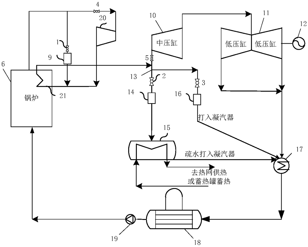
[0039] refer to figure 1 , a system that realizes the switching operation of the thermal power unit in three states, including the high-pressure bypass water spraying temperature reduction and pressure reduction pipeline, the low pressure bypass water spraying temperature reduction and pressure reduction pipeline, the heating network heater and the centralized control system of the power plant The bypass heating control module sends all the steam to the heat network heater for heat exchange through the high-pressure and low-pressure water spraying, temperature reduction and decompression bypass, which can realize that the steam turbine of the thermal power unit does not enter the steam at all, so that the cogeneration unit can be completely switched to become The single heating boiler operation mode supplies external heat.

[0040] Specifically, the boiler 6 is connected to the high-pressure cylinder 20, the boiler 6 is provided wit...

Embodiment 2

[0065] Embodiment 2 (single heating mode)

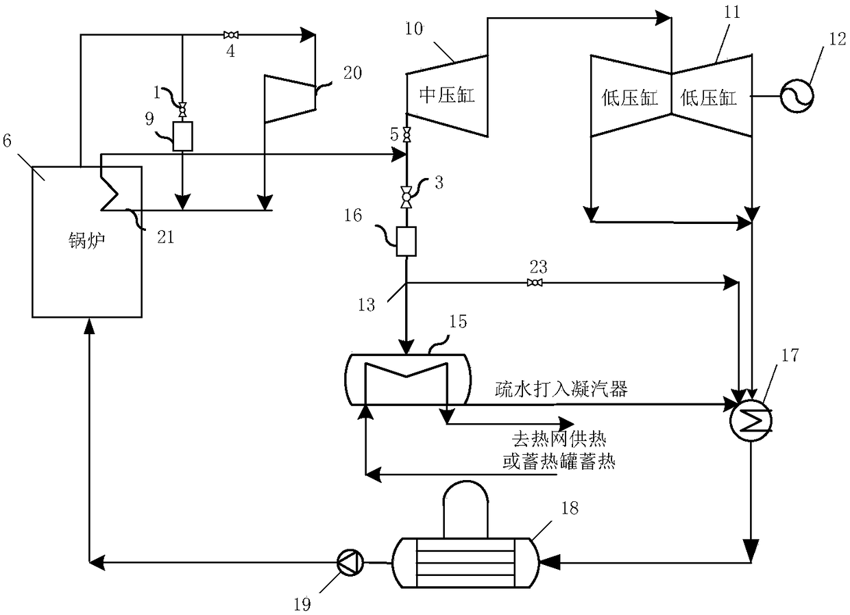
[0066] refer to figure 2 , the difference from Example 1 is that the low-pressure bypass water spray desuperheating and pressure reducing pipeline includes a low-pressure water spraying desuperheating and pressure reducing device 16 and a low-pressure inlet cut-off valve 23, and the low-pressure water spraying desuperheating and pressure reducing device A bypass regulating valve 3 is provided at the inlet of 16, and the hot network heater is connected in parallel with the inlet shut-off valve 23.

[0067] The low-pressure inlet stop valve 6 is set on the pipeline connected to the condenser, so that the existing two-stage bypass can be used to the greatest extent, so that the system modification cost is the lowest. However, such a connection method requires that the original Class I or Class II bypass flow should be large enough, on the one hand, it must meet the minimum cooling flow requirements of the reheater, and on the other ha...

Embodiment 3

[0068] Embodiment 3 (single heating mode)

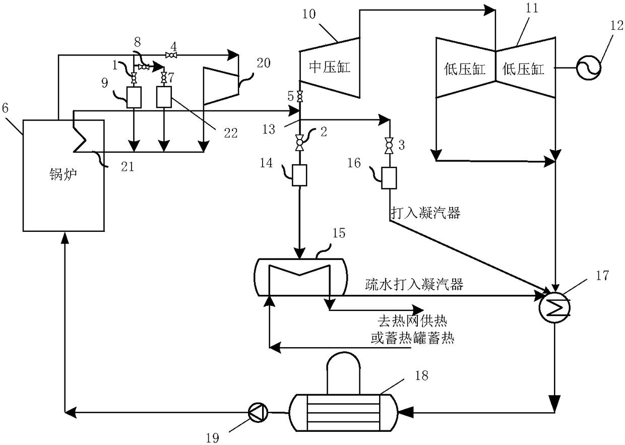
[0069] refer to image 3 , and embodiment 1 is different in that, between the boiler 6 and the high-pressure cylinder 20, there is also a large-flow high-pressure bypass water spraying temperature reduction and decompression pipeline, and the large-flow high-pressure bypass water spraying temperature reduction and decompression The pipeline is connected in parallel with the high-pressure bypass water spraying desuperheating and decompression pipeline, and the high-flow high-pressure bypass water spraying desuperheating and decompression pipeline includes a large-flow water spraying desuperheating and pressure reducing device 22. The inlet of the temperature and pressure reducer 22 is connected with a high pressure inlet stop valve 8 and a pressure reducing valve 7 . The high-pressure inlet shut-off valve 8 is connected to a boiler, and the outlet of the large-flow water spray desuperheater 22 is connected to a reheater 21 .

[0070...


PUM


Abstract

The invention relates to a system for realizing three-state switching operation of a thermoelectric unit. The system comprises a high-pressure bypass water spray temperature and pressure reduction pipeline, a low-pressure bypass water spray temperature and pressure reduction pipeline and a heat network heater. The high-pressure bypass water spray temperature and pressure reduction pipeline is arranged between a boiler and a high-pressure cylinder. The high-pressure bypass water spray temperature and pressure reduction pipeline and the low-pressure bypass water spray temperature and pressure reduction pipeline both comprise water spray temperature and pressure reduction devices. The heat network heater is connected with the portions, behind the water spray temperature and pressure reductiondevices, of the pipelines. Steam generated by the boiler is sent to the heat network heater through the high-pressure bypass water spray temperature and pressure reduction pipeline and the low-pressure bypass water spray temperature and pressure reduction pipeline. The heat network heater is connected with an external heating system. According to the system, the existing or newly added high-pressure bypass water spray temperature and pressure reduction system and low-pressure bypass water spray temperature and pressure reduction system are utilized, so that the reconstruction workload is small, the thermoelectric unit can be completely switched to three operation states, and the maximum depth peak regulation can be achieved.

Description

technical field [0001] The invention relates to the field of unit bypass applications, in particular to the application field of using primary and secondary bypasses to switch boilers from thermoelectric units to three states, and in particular to a system for realizing the switching operation of thermoelectric units to three states. Background technique [0002] We all know that electric energy cannot be stored, so the power plant needs to generate as much electricity as the user needs, so as not to cause energy waste. However, in the power system, the demand load of each power plant is constantly changing. In order to maintain the balance of active power and keep the system frequency stable, the power generation department needs to change the power generation of the generator to adapt to the change of power load. It's called peak shaving. [0003] In China's three northern regions, the power market capacity is abundant, gas turbines, pumped storage and other peak-adjustab...

Claims


Application Information

Patent Timeline
Patent Type & Authority Applications(China)
IPC IPC(8): F01K11/00F01K11/02F01K13/00F01K13/02
CPCF01K11/00F01K11/02F01K13/00F01K13/02
Inventor 杨豫森林秀华陈辉崔华徐波谭智王小英
Owner HEPU ENERGY ENVIRONMENTAL TECHNOLOGY CO LTD
Why Eureka
Try Eureka