
Flue gas desulfurization absorber interactive spray system

A desulfurization absorption tower and spray system technology, applied in the field of flue gas desulfurization absorption tower interactive spray system, can solve the problems of large deformation of the main pipe, uneven nozzle flow, large change of pipe diameter, etc., to increase height and shorten Renovation construction period and effect of reducing remodeling workload

Inactive Publication Date: 2015-08-26
ZHEJIANG TIANDI ENVIRONMENTAL PROTECTION TECH CO LTD
View PDF4 Cites 5 Cited by
  • Summary
  • Abstract
  • Description
  • Claims
  • Application Information

AI Technical Summary

Problems solved by technology

This type of spray structure adopts a single-side inlet pipe, and the spray slurry has a long pipeline during the transportation process, and the diameter of the pipe varies greatly, and there is a large loss along the process, resulting in uneven flow of the nozzle and affecting the spray. The uniform distribution of layers reduces the spray absorption efficiency and ultimately affects the desulfurization and waste removal effect of the entire system
When the single-side spraying main pipe spray system is running, because the distribution of the slurry in the pipe is uneven, the load of the spray system is also uneven, and the deformation of the main pipe itself is relatively large. Hanging or lifting installation The internal steel beams also cause the problem of stress concentration, so during the design and installation of the absorption tower, it is necessary to pay attention to the load distribution of the sprinkler system, which increases the design requirements and installation difficulty

Method used


Image

  • Flue gas desulfurization absorber interactive spray system
  • Flue gas desulfurization absorber interactive spray system

Examples


Embodiment Construction

[0016] The present invention will be further described below in conjunction with the examples. The description of the following examples is provided only to aid the understanding of the present invention. It should be pointed out that for those skilled in the art, without departing from the principle of the present invention, some improvements and modifications can be made to the present invention, and these improvements and modifications also fall within the protection scope of the claims of the present invention.

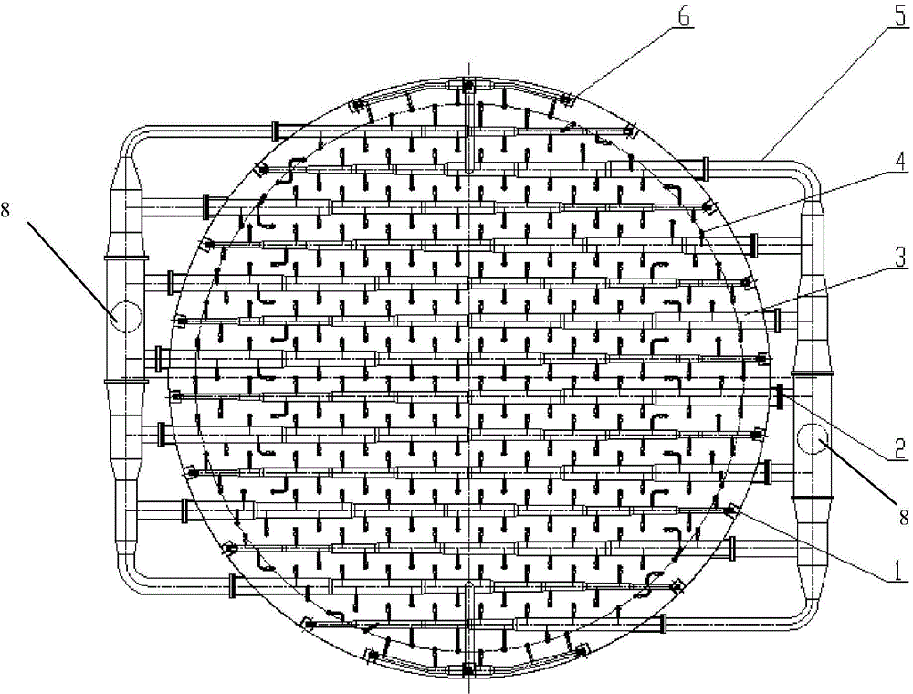
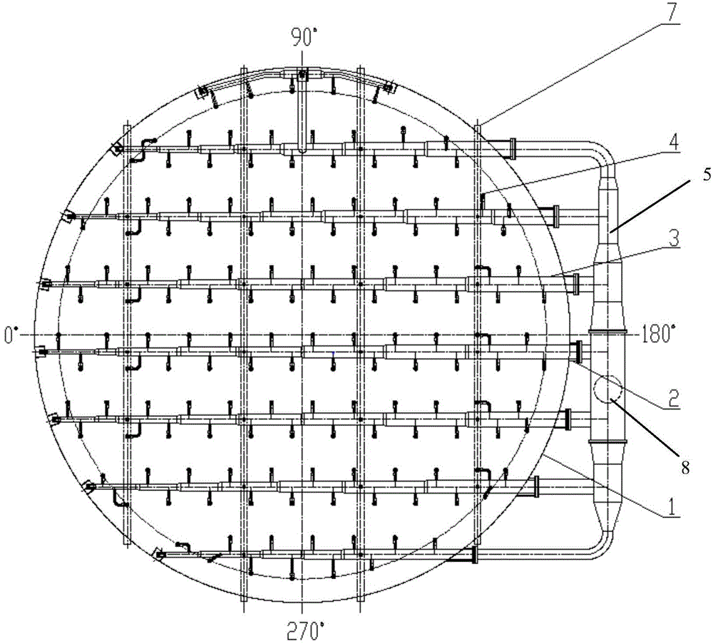
[0017] The circulating interactive spray system of the desulfurization absorption tower of the present invention can be arranged in layers in the absorption tower 1, and the spray slurry is limestone slurry, which is transported from the slurry area at the bottom of the absorption tower through the external circulation slurry pipe 5 to the spray mother via the circulating slurry pump. The pipe is sprayed and circulated continuously. Each spray layer is mainly com...


PUM


Abstract

The invention discloses a flue gas desulfurization absorber interactive spray system which is parallelly arranged in an absorber body in a layered manner. Each layer comprises a plurality of spray main pipes, spray nozzles, supporting steel beams and supports, the spray main pipes are sequentially parallelly arranged in opposite directions, the diameter of each spray main pipe is reduced link by link in a stepped manner from a near end to a far end, the inside of the pipes is uniform in flow speed, the spray nozzles are the same in flow, the spray main pipes penetrate a spigot joint welded on the absorber body, are connected with external circulating slurry pipes in a flanged manner and extend into the absorber body, small ends of the spray main pipes are placed on the supports, the middles of the spray main pipes are fixed onto the supporting steel beams through hoops, and the external circulating slurry pipes on each layer are connected with the main pipes perpendicular to the external circulating slurry pipes. The system has the advantages that the liquid-gas ratio of a desulfurization system is further increased, the system is convenient to arrange, manufacture is correspondingly simplified, and mounting time is also shortened. The arrangement space of the spray main pipes is saved, the height of an absorber is reduced, the lift of a circulating slurry pump is reduced, and desulfurization electricity consumption is reduced.

Description

technical field [0001] The invention relates to the technical field of flue gas desulfurization, more specifically, it relates to an interactive spraying system of a flue gas desulfurization absorption tower. Background technique [0002] my country's power plants and industrial boilers use coal as fuel, and produce SO in the process of combustion. 2 and other harmful substances, in order to remove SO in the flue gas 2 And to meet the increasing environmental protection requirements, domestic thermal power plants mostly use limestone / gypsum wet flue gas desulfurization technology. [0003] The spray system of the absorption tower is an important part of the wet desulfurization system. The existing common spray structure of the desulfurization absorption tower is a single-side spray main pipe structure. The circulating slurry enters the spray main pipe through the slurry pipe outside the tower, and then The various branch pipes separated from the spray main pipe distribute ...

Claims


Application Information

Patent Timeline
IPC IPC(8): B01D53/80B01D53/50
Inventor 吴国潮朱松强孟炜胡达清沈海涛单新宇陈文华刘寒梅葛春亮钟莎徐轶伦
Owner ZHEJIANG TIANDI ENVIRONMENTAL PROTECTION TECH CO LTD
Learn More