Keycap structure and button

A technology of keycaps and buttons, which is applied in the field of keycap structure and its buttons, can solve the problems of time-consuming and labor-intensive, high assembly failure rate, etc., and achieve the effect of improving manufacturing yield, improving functionality and practicality

Active Publication Date: 2018-08-31
DARFON ELECTRONICS (SUZHOU) CO LTD +1
View PDF3 Cites 6 Cited by
  • Summary
  • Abstract
  • Description
  • Claims
  • Application Information

AI Technical Summary

Problems solved by technology

[0005] In view of the problems in the prior art, the present invention provides a key cap and its key junction, which adopts the method of directly laying the first wire circuit and the second wire circuit on the top surface and the bottom surface of the key cap respectively, and makes the second wire circuit avoid the key The design of the snap-fit ​​structure on the bottom surface of the cap, the induction device or the display device is attached to the first wire circuit, so that the flexible circuit board can carry out the electrical signal of the induction device or the display device through the first wire circuit and the second wire circuit The transmission does not require additional snap-in structural sheets, so the present invention can effectively solve the problems of time-consuming and labor-intensive key assembly process and high assembly defect rate mentioned in the prior art, thereby improving the manufacturing yield of the keyboard, and can pass Additional functions (such as fingerprint recognition function or image display function, etc.) provided by the induction device or display device attached to the first wire circuit further enhance the functionality and practicability of the button

Method used


Image

  • Keycap structure and button
  • Keycap structure and button
  • Keycap structure and button

Examples


Embodiment Construction

[0033] In order to have a further understanding of the purpose, structure, features, and functions of the present invention, the following detailed descriptions are provided in conjunction with the embodiments.

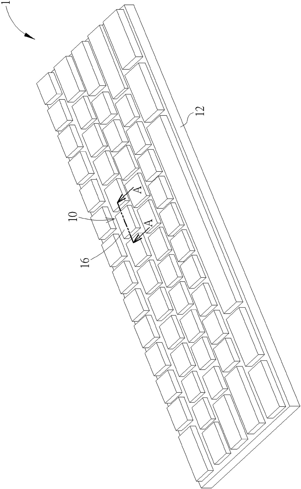
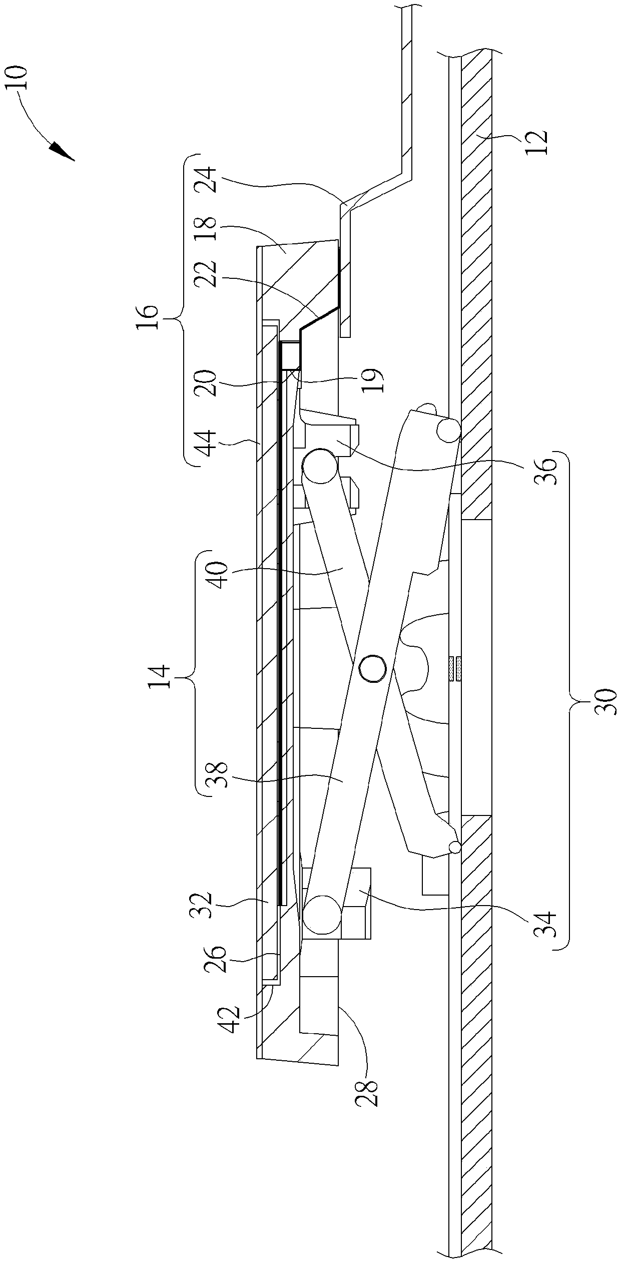
[0034] see figure 1 as well as figure 2 , figure 1 It is a three-dimensional schematic diagram of the keyboard 1 proposed according to an embodiment of the present invention, figure 2 for figure 1 A schematic cross-sectional view of the button 10 along the section line A-A. Such as figure 1 as well as figure 2 As shown, the keyboard 1 includes a plurality of keys 10 and a base plate 12 , and the plurality of keys 10 are disposed on the base plate 12 for the user to press to execute the function that the user wants to input. It should be noted that the keyboard 1 can be preferably applied to a portable electronic device (such as a notebook computer keyboard or a folding keyboard device) that generally has an opening and closing mechanism composed of an upper c...


PUM


Abstract

A keycap structure is combined with an elevating mechanism so as to move between a pressing position and a non-pressing position. The keycap structure comprises a keycap, a first lead circuit, a second lead circuit and a flexible circuit board. The keycap possesses a top surface, a bottom surface and a clamping structure. The top surface and the bottom surface are opposite to each other. The clamping structure is formed through protruding from the bottom surface so as to be clamped and connected to the elevating mechanism. The first lead circuit is arranged on the top surface so as to connectan induction device or display equipment attached to the top surface. The second lead circuit is arranged on the bottom surface, avoids the position of the clamping structure and passes through the keycap so as to connect the first lead circuit. The flexible circuit board is connected to the second lead circuit and carries out electric signal transmission of the induction device or the display equipment via the first lead circuit and the second lead circuit. The problems of the time consuming and labor consuming and the high assembling failure rate of a button assembling process can be effectively solved, the manufacturing yield of a keyboard is improved, and through the additional function of the induction device, the functionality and the practicality of a key are increased.

Description

technical field [0001] The present invention relates to a keycap structure and its keys, in particular to a card in which a first wire circuit and a second wire circuit are respectively arranged directly on the top surface and the bottom surface of the keycap and the second wire circuit is avoided from the bottom surface of the keycap. The combined structure of the keycap structure and its keys. Background technique [0002] As far as current personal computer usage habits are concerned, the keyboard is one of the indispensable input devices for inputting characters, symbols or numbers. Not only that, but all consumer electronic products in daily life or large-scale processing equipment used in the industry need to be equipped with a key structure as an input device for users to perform operations such as character input. [0003] In practical applications, in order to make the keys have other application functions (such as fingerprint recognition, image display, etc.), the...

Claims


Application Information

Patent Timeline
Patent Type & Authority Applications(China)
IPC IPC(8): H01H13/02H01H13/14
CPCH01H13/023H01H13/14H01H2219/002
Inventor 胡才荣张友志
Owner DARFON ELECTRONICS (SUZHOU) CO LTD
Why Eureka
Try Eureka