Plug-in cable elbow type head detacher
A technology of cable elbow and remover, which is applied in the direction of overhead line/cable equipment, equipment for connecting/terminating cables, etc. It can solve the problem of adhesion between the elbow head and the conical insulating pillar porcelain bottle of the cabinet, high purchase price, and poor disassembly effect. Poor and other problems, to achieve the effect of increasing positioning accuracy and stability, low manufacturing cost, and shortening disassembly time
- Summary
- Abstract
- Description
- Claims
- Application Information
AI Technical Summary
Problems solved by technology
Method used
Image
Examples
Embodiment 1
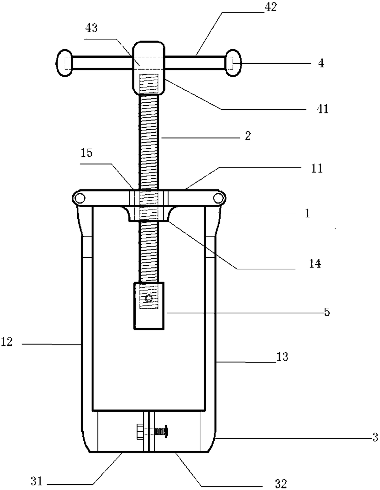
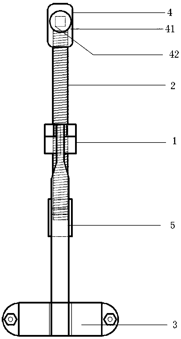
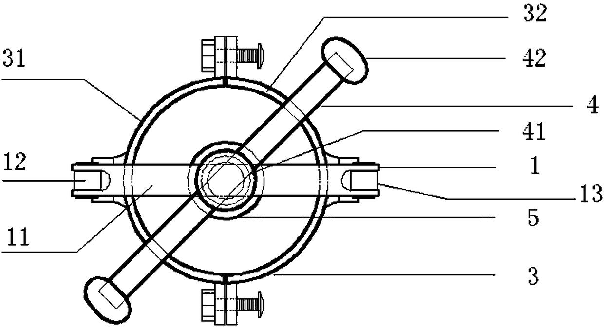
[0036] This embodiment discloses a plug-in cable elbow remover, such as figure 1 , figure 2 with image 3 As shown, it includes a force application bracket 1, a positioning screw 2, and a hoop 3. The lower part of the force application bracket 1 is provided with a hoop 3 for holding the cable elbow, and the hoop 3 includes a first arc hoop body 31 and a second arc-shaped hoop body 32, the two ends of the first arc-shaped hoop body 31 are detachably connected with the two ends of the second arc-shaped hoop body 32, and the force-applying bracket 1 and the The positioning screw 2 is screwed together, and the positioning screw 2 can reciprocate along the axial direction of the hoop 3 . When removing the plug-in cable elbow, use the hoop 3 to hold the elbow firmly, and rotate the positioning screw 2 to move the positioning screw 2 in the direction of the hoop 3 until the positioning screw 2 touches the conductive rod and continues to rotate The positioning screw 2 squeezes the...
Embodiment 2
[0053] This embodiment discloses a plug-in cable elbow remover, such as Figure 4 or Figure 5 shown.
[0054] The difference between this embodiment and embodiment 1 is that the hoop 3 is hinged to the force applying bracket 1 .
[0055] The first arc-shaped hoop body 31 of the hoop 3 is hinged on the first vertical bar 12, and the second arc-shaped hoop body 32 of the hoop 3 is hinged on the second vertical bar 13 in a two-degree-of-freedom manner. Hinged, that is, the first arc-shaped hoop 31 and the second arc-shaped hoop 32 can rotate inside the force-applying bracket 1 around the hinge with the force-applying bracket 1 in the plane where the force-applying bracket 1 is located.
[0056] Specifically, you can press Figure 4 As shown, the first vertical bar 12 and the second vertical bar 13 are respectively provided with a first connecting plate 16 and a second connecting plate 17 . The first arc-shaped hoop body 31 of the hoop 3 is provided with a first connecting gr...
PUM
 Abstract
Description
Claims
Application Information
 - R&D
- Intellectual Property
- Life Sciences
- Materials
- Tech Scout
- Unparalleled Data Quality
- Higher Quality Content
- 60% Fewer Hallucinations
Browse by: Latest US Patents, China's latest patents, Technical Efficacy Thesaurus, Application Domain, Technology Topic, Popular Technical Reports.
© 2025 PatSnap. All rights reserved.Legal|Privacy policy|Modern Slavery Act Transparency Statement|Sitemap|About US| Contact US: help@patsnap.com


