Electrolyzed water generation device and production device for water for dialysate preparation and method for electrolyzed water generation that use same

A technology for generating device and electrolyzing water, applied in electrochemical water/sewage treatment, dialysis system, etc., which can solve the problems of oxygen retention, difficulty in increasing dissolved hydrogen concentration, and oxygen discharge.

Active Publication Date: 2018-08-31
NIKHON TRIM KO LTD
View PDF12 Cites 0 Cited by
  • Summary
  • Abstract
  • Description
  • Claims
  • Application Information

AI Technical Summary

Problems solved by technology

Also, in this case, since the water flow in the anode chamber is suppressed, it is difficult for the oxygen in the bubble state to be discharged from the anode chamber together with the electrolyzed water, so that the oxygen in the bubble state stays in the anode chamber
When the oxygen gas in this bubble state stays attached to the surface of the anode power supply body, etc., the water supplied to the surface of the power supply body decreases, so electrolysis in th

Method used


Image

  • Electrolyzed water generation device and production device for water for dialysate preparation and method for electrolyzed water generation that use same
  • Electrolyzed water generation device and production device for water for dialysate preparation and method for electrolyzed water generation that use same
  • Electrolyzed water generation device and production device for water for dialysate preparation and method for electrolyzed water generation that use same

Examples


Embodiment Construction

[0033] Hereinafter, one embodiment of the present invention will be described with reference to the drawings.

[0034] (first invention)

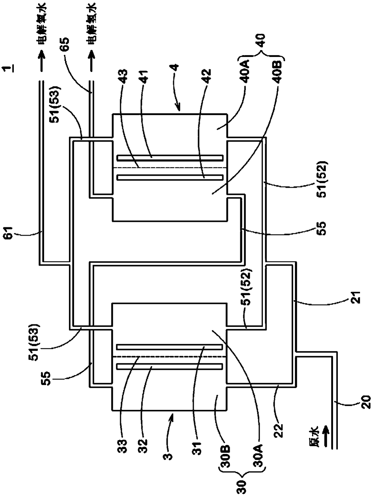
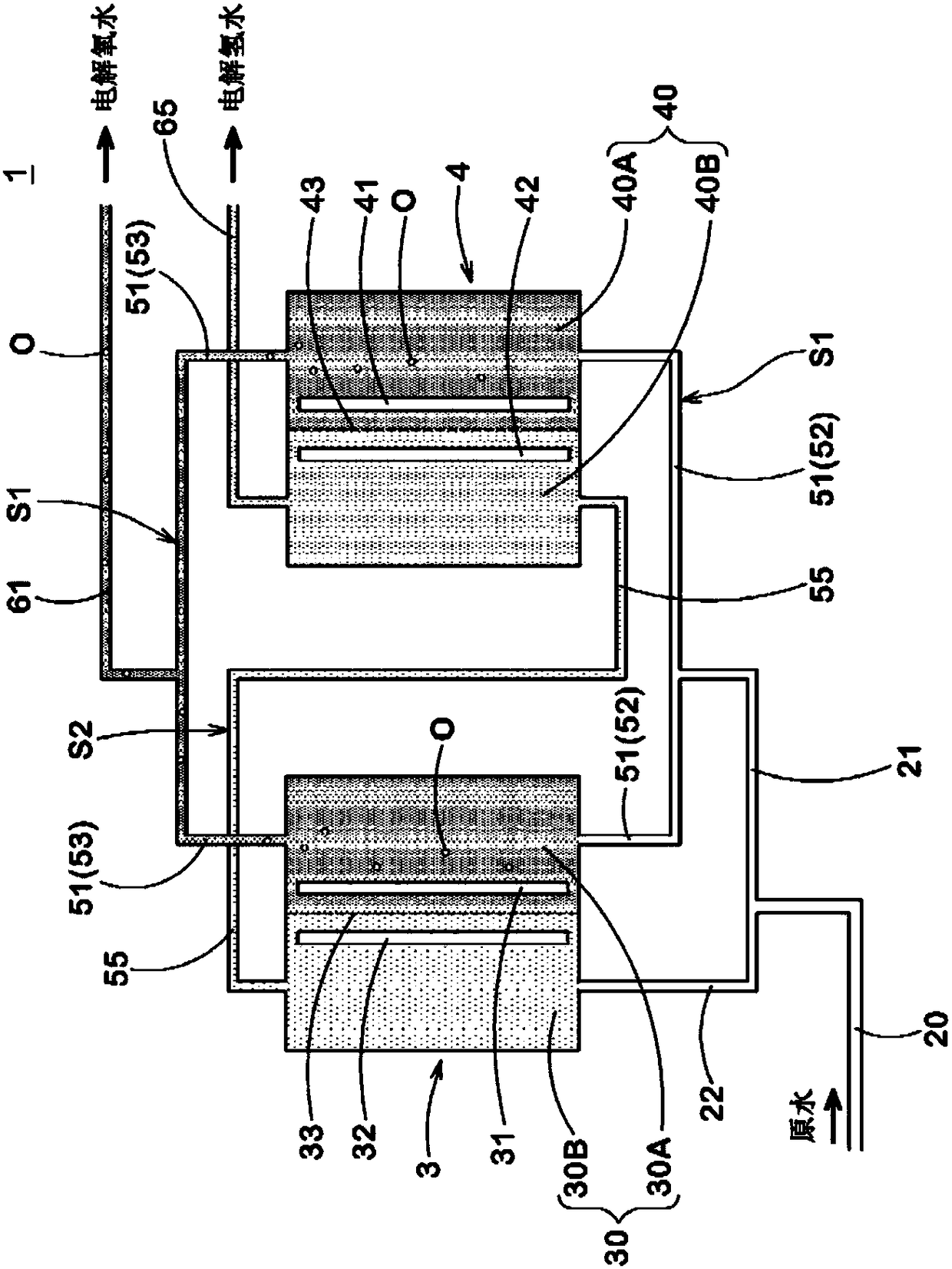
[0035] figure 1 The schematic structure of the flow path of the electrolyzed water generator 1 which is embodiment of the 1st invention is shown. The electrolyzed water generator 1 is widely used in the production of domestic drinking water, in addition to the production of dialysate preparation water, for example.

[0036] The electrolyzed water generator 1 includes a plurality of electrolytic cells 3, 4, . . . . figure 1 In , the electrolyzed water generator 1 provided with a pair of electrolytic cells 3 and 4 is shown. The electrolyzed water generator 1 may include three or more electrolytic cells 3, 4, . . . .

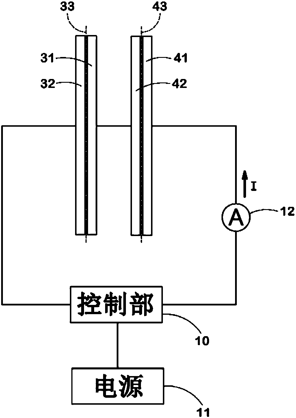
[0037] The electrolytic cell 3 has: an electrolysis chamber 30 for electrolyzing water; a first power supply body 31 and a second power supply body 32 disposed opposite to each other in the electrolysis chamber 30; The diap...


PUM


Abstract

An electrolyzed water generation device 1 comprising a plurality of electrolysis chambers 30, 40, ... for the electrolysis of water. Each electrolysis chamber 30, 40, ... has arranged therein: a firstpower feeder 31, 41, ... and a second power feeder 32, 42, ... arranged facing each other; and a partition membrane 33, 43, ... that divides the electrolysis chamber 30, 40,... into a first polar chamber 30A, 40A on the first power feeder 31, 41 ... side and a second polar chamber 30B, 40B, ... on the second power feeder 32, 42, ... side. A solid polymer membrane is used as the partition membrane33, 43, .... At least two electrolysis chambers 30, 40 are connected by parallel water channels 51 that connect the first polar chambers 30A, 40A in parallel and by a serial water channel 55 that connects the second polar chambers 30B, 40B in series.

Description

technical field [0001] The present invention relates to an electrolyzed water generating device and the like which electrolyze water to generate electrolyzed water. Background technique [0002] Conventionally, there is known an electrolyzed water generator that includes an electrolyzer having electrolyzed chambers partitioned by a diaphragm, and electrolyzes tap water or the like supplied to the electrolyzed chamber to generate electrolyzed hydrogen water in which hydrogen is dissolved. For example, Patent Document 1 discloses an electrolyzed water generator including two electrolytic cells connected in series in order to increase the dissolved hydrogen concentration. [0003] prior art literature [0004] patent documents [0005] Patent Document 1: Japanese Patent No. 4417707 [0006] In the electrolyzed water generating device described above, the electrolyzed hydrogen water is generated in the cathode chamber in which the cathode power supply is disposed. At this ti...

Claims


Application Information

Patent Timeline
IPC IPC(8): C02F1/46A61M1/14
CPCA61M1/14C02F1/46
Inventor 橘孝士
Owner NIKHON TRIM KO LTD
Why Eureka
Try Eureka