
Interbody fusion cage

An intervertebral fusion device and fusion device technology, applied in the field of intervertebral fusion devices, can solve the problems of reducing the bearing surface of the fusion device, aggravating the risk of slippage, and poor supporting effect, so as to achieve good fixation effect, reduce the difficulty and risk of surgery, and effectively The effect of support

Pending Publication Date: 2018-09-04
黄振强
View PDF1 Cites 5 Cited by
  • Summary
  • Abstract
  • Description
  • Claims
  • Application Information

AI Technical Summary

Problems solved by technology

However, on the one hand, after opening, only the front end of the cage body contacts the endplate bone surface of the vertebral body, which reduces the bearing surface of the cage, and the supporting effect is poor; on the other hand, considering the obstruction of intervertebral disc tissue and residual endplate cartilage, In addition, the front end of the fusion cage generally has no dentate protrusion, and the expanded fusion cage has insufficient anti-slip function and the function of stabilizing the upper and lower vertebral bodies. In addition, considering that the front end of the intervertebral space is connected by the annulus fibrosus and the anterior longitudinal ligament, the increase in the height of the intervertebral space is limited. This makes the front end of the fusion cage easy to be restricted during the opening process, causing the fusion cage to slide back as a whole, exacerbating the risk of slippage, and pedicle screws are still required for fixation

Method used


Image

  • Interbody fusion cage
  • Interbody fusion cage
  • Interbody fusion cage

Examples


Embodiment Construction

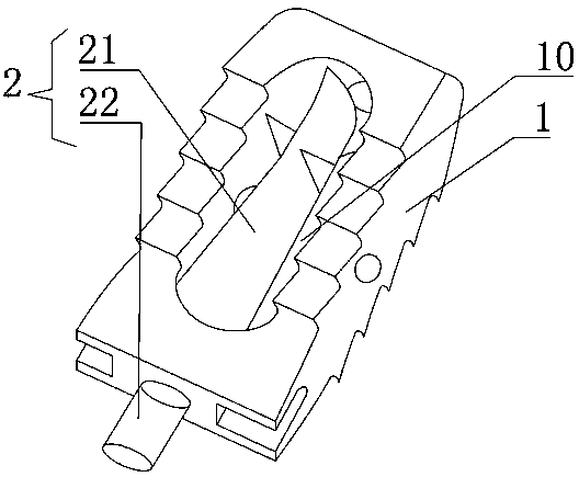
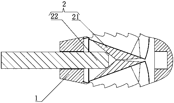
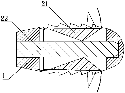
[0026] In order to make the object, technical solution and advantages of the present invention clearer, the implementation manners of the present invention will be further described in detail below in conjunction with the accompanying drawings. Apparently, the described embodiments are some, not all, embodiments of the present invention. Based on the described embodiments of the present invention, all other embodiments obtained by persons of ordinary skill in the art without creative efforts shall fall within the protection scope of the present invention.

[0027] Such as Figure 1-5 As shown, it shows an intervertebral fusion device provided by the present invention. The intervertebral fusion device is used to be inserted into the space between vertebral bodies 100, and includes a fusion device body 1 and an expander 2 disposed in the fusion device body 1, a bone graft groove 10 is arranged in the fusion device body 1, and The expander 2 is disposed in the bone graft groove...


PUM


Abstract

The invention provides an interbody fusion cage used for being disposed into vertebral body gaps. The interbody fusion cage comprises a fusion cage body and an expander. A bone grafting groove is formed in the fusion cage body. The expander is arranged in the bone grafting groove, and comprises an expanding device and an adjusting device for adjusting the expanding device. The expanding device hasan initial state and an expansion state. In the initial state, the expanding device can be completely accommodated in the bone grafting groove, and in the expansion state, the expanding device can extend out of the bone grafting groove after expansion. By the adjusting device, the expanding device can be switched from the initial state to the expansion state and is nailed into vertebral bodies. The interbody fusion cage has the advantages that the fusion cage can be immediately fastened between the upper vertebral body and the lower vertebral body, the anti-slip effect and the support effectcan be guaranteed, pedicle screw fixation can be avoided, and surgical difficulty and risk are reduced; the interbody fusion cage can support the vertebral bodies effectively, has a good support function, and can be prevented from being influenced by blocking of intervertebral disk tissues and residual end plate cartilages; the fixation effect is good, and the anti-slip function of the interbody fusion cage is guaranteed effectively.

Description

technical field [0001] The invention relates to the technical field of medical instruments, in particular to an intervertebral fusion device. Background technique [0002] The intervertebral fusion device is placed in the intervertebral space after the lumbar intervertebral disc is removed to restore the height of the intervertebral space, support the load of the upper and lower vertebral bodies, and integrate the upper and lower vertebral bodies into one. The existing straight intervertebral fusion device has been clinically verified for many years and is an effective and safe device. However, due to the concave shape of the upper and lower terminal surfaces of the vertebral body, the height of the intervertebral space is short at both ends and long in the middle. Coupled with the differences in the individual, age, and physical condition of patients, the bone surfaces of the upper and lower endplates of the intervertebral space are irregular. The existing intervertebral f...

Claims


Application Information

Patent Timeline
IPC IPC(8): A61F2/44A61B17/70
CPCA61B17/70A61F2/4455A61B2017/7073
Inventor 黄振强
Owner 黄振强
Learn More