A bracket for gear quenching

A technology of gears and positioning gears, which is applied in the direction of quenching devices, furnaces, furnace types, etc., can solve the problems of high production cost of gears and easy damage of gears, and achieve the effects of reducing processing costs, uniform heating, and reducing production costs

Inactive Publication Date: 2019-06-18
平湖市永成齿轮配件厂
View PDF4 Cites 0 Cited by
  • Summary
  • Abstract
  • Description
  • Claims
  • Application Information

AI Technical Summary

Problems solved by technology

[0004] The invention provides a bracket for gear quenching, which aims to solve the technical problem in the prior art that the gear is easily damaged during the quenching process and the production cost of the gear is high

Method used


Image

  • A bracket for gear quenching
  • A bracket for gear quenching

Examples


Embodiment Construction

[0014] A bracket for gear quenching of the present invention will be further described below in conjunction with the accompanying drawings. The following examples are only used to help those skilled in the art understand the present invention, and are not intended to limit the present invention.

[0015] A bracket for gear quenching is used for positioning the gear so as to facilitate placing the gear in a quenching furnace for heat treatment.

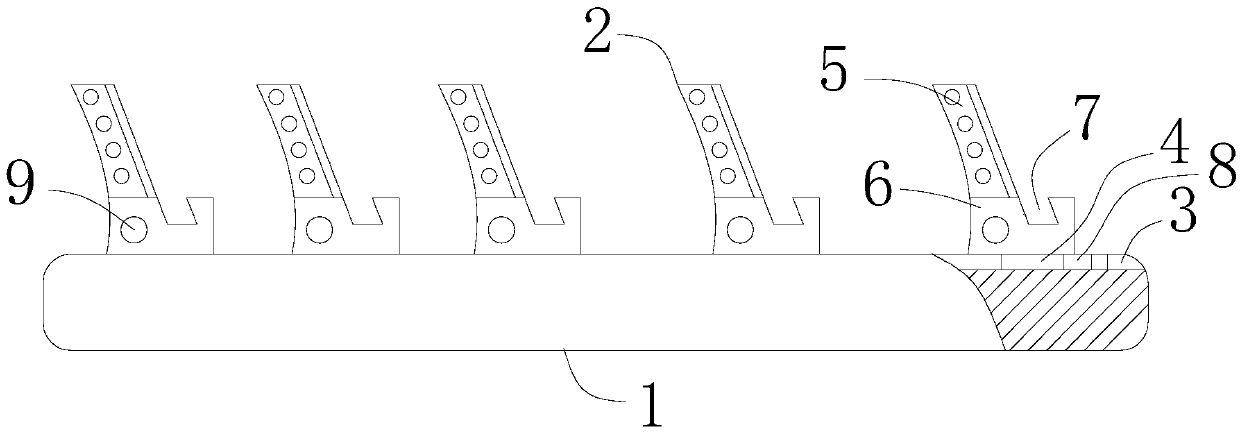
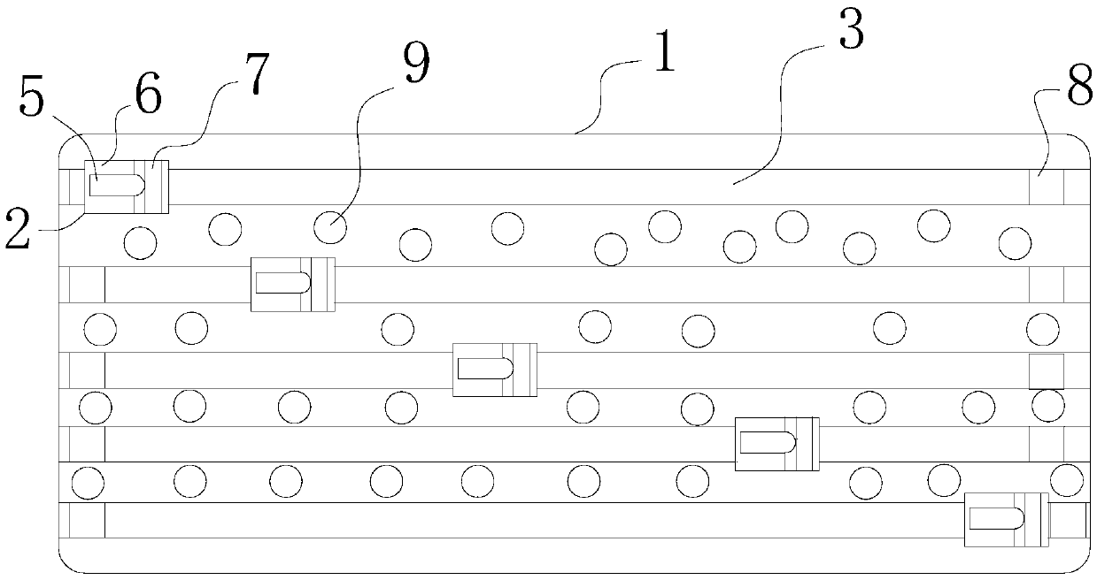
[0016] Such as figure 1 , figure 2 , the bracket used for gear quenching includes a base 1, and positioning blocks 2 for positioning gears are evenly distributed on the base 1, and the positioning blocks 2 are slidably connected to the base 1, and the base 1 is provided with A chute 3, on the positioning block 2 is provided with a slider 4 that cooperates with the chute 3, the cross-sectional shape of the chute 3 is a trapezoid with a narrow top and a wide bottom, this solution can effectively avoid the sliding block 4 slides out o...


PUM


Abstract

The invention relates to a gear machining auxiliary tool, in particular to a bracket for gear quenching. The bracket for gear quenching aims at solving the technical problem that the gear production cost is high since a gear is prone to damage during quenching treatment in the prior art. The bracket for the gear quenching is characterized in that locating blocks are uniformly arranged on a base; the locating blocks are connected with the base in a sliding manner; in addition; and the locating blocks comprise abutting and connecting parts and locating parts. An included angle between each gearand a horizontal plane is 30-60 degrees due to the abutting and connecting parts, so that the gears are obliquely located on the base, a space occupied by each gear on the base is reduced, more gearscan be placed on the base, and the quenching cost of the gears is lowered. The gears are located through the locating blocks, and the contact area between each gear and the base is reduced, so that the gears are heated uniformly, the gears are not prone to cracking after being quenched, and the machining cost of the gears is lowered.

Description

technical field [0001] The invention relates to an auxiliary tool for gear processing, in particular to a bracket for gear quenching. Background technique [0002] The machining process of gears includes multiple processes. For example, the gears need to be quenched and heat treated after machining to obtain better mechanical properties of the gears. [0003] In the prior art, when the gear is quenched, the gear is first placed on the steel plate, and then the gear on which the steel plate is placed is placed in a quenching furnace for heating. This quenching method causes the gear and the steel plate to have a large contact area, and defects such as cracks are likely to occur on the contact surface of the gear and the steel plate during quenching treatment, which increases the production cost of the gear. In addition, the gears are laid flat on the steel plate so that the gears occupy a large area on the steel plate, which reduces the number of gears placed on the steel pl...

Claims


Application Information

Patent Timeline
Patent Type & Authority Patents(China)
IPC IPC(8): C21D9/32C21D1/62
CPCC21D1/62C21D9/32
Inventor 屠卫中
Owner 平湖市永成齿轮配件厂
Why Eureka
Try Eureka