
Construction method for mutually-buckled underground pipe gallery

A construction method and technology of underground pipe gallery, applied in artificial islands, water conservancy projects, underwater structures, etc., can solve the problems of complex process, low efficiency, difficult prefabrication of prefabricated wall panels, etc., to simplify the process of assembly and construction, manufacturing Simple, easy connection and effect of the adjustment process

Active Publication Date: 2018-09-04
CHINA METALLURGICAL CONSTR ENG GRP
View PDF7 Cites 0 Cited by
  • Summary
  • Abstract
  • Description
  • Claims
  • Application Information

AI Technical Summary

Problems solved by technology

[0005] In view of the above-mentioned deficiencies in the prior art, the technical problem to be solved by the present invention is to provide a construction method for an interlocking underground pipe gallery, which avoids the difficulty of prefabricating prefabricated wall panels, and the process of combining prefabricated wall panels into a superimposed wall is complex and efficient. The problem is that only one structural type of prefabricated wall panels is needed to achieve the side wall of the entire pipe gallery, which simplifies the entire assembly and construction process and improves the construction efficiency.

Method used


Image

  • Construction method for mutually-buckled underground pipe gallery
  • Construction method for mutually-buckled underground pipe gallery
  • Construction method for mutually-buckled underground pipe gallery

Examples


specific Embodiment 1

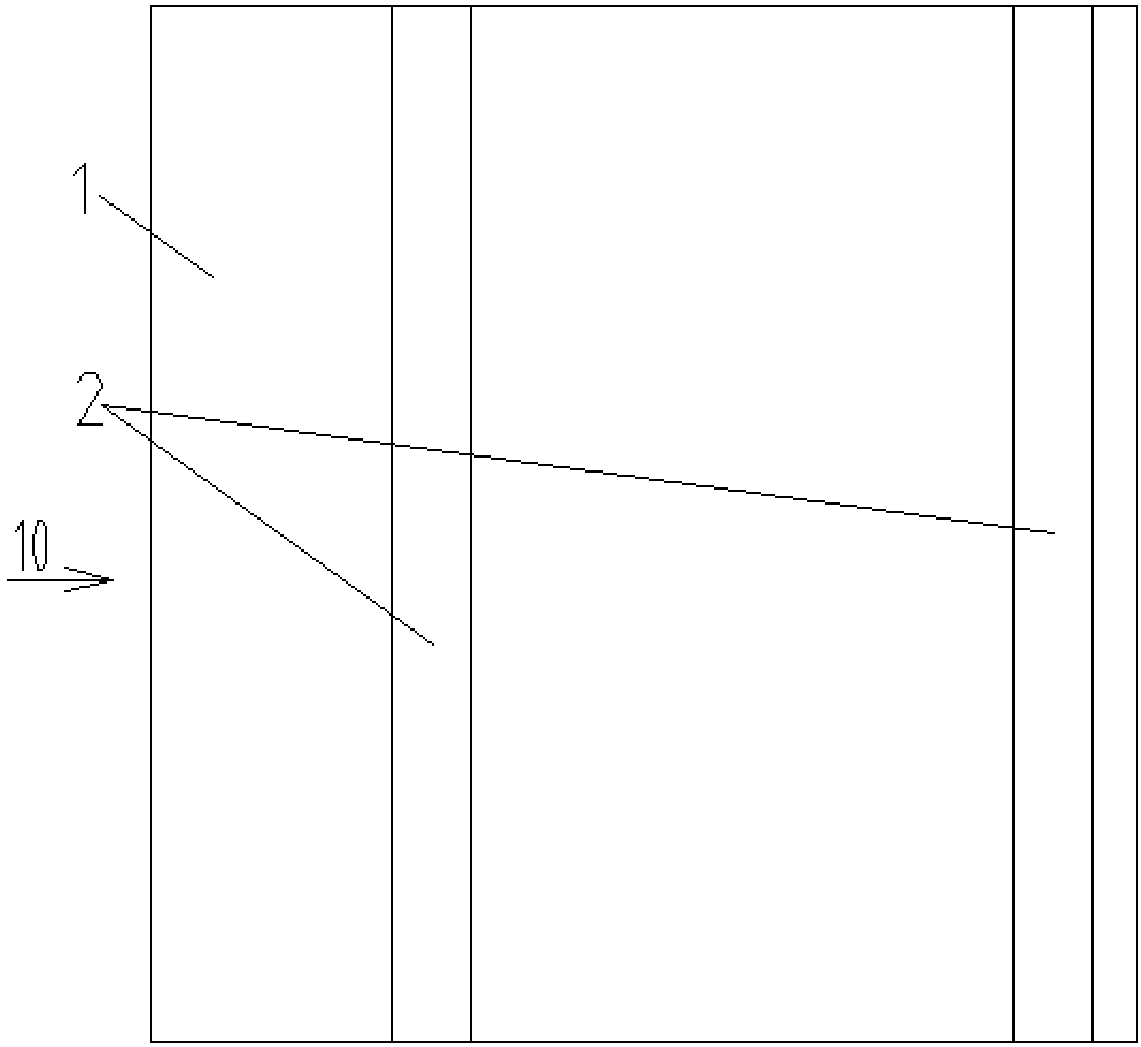
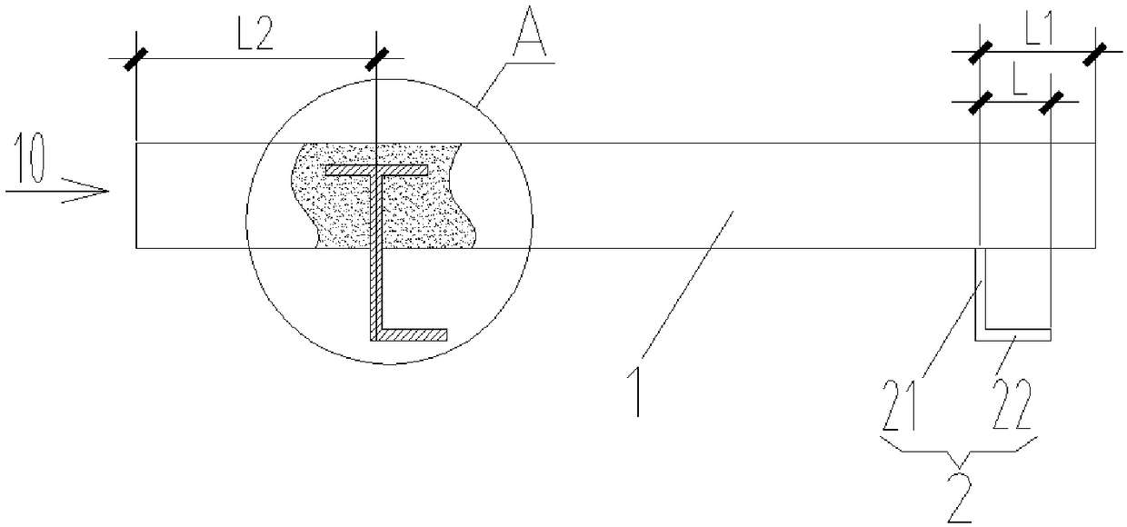
[0060] see figure 1 , figure 2 , the construction method of the interlocking type underground pipe gallery of the specific embodiment 1, including several interlocking type single-piece prefabricated wall panels 10 used in the construction process, and the interlocking type single-piece prefabricated wall panels 10 include vertical The wallboard 1, along the length direction of the wallboard 1, on one side of the wallboard 1, two buckle ribs 2 extending in the vertical direction and having an "L" shape in horizontal section, the buckle ribs The board 2 includes a vertical side 21 perpendicular to the wallboard 1 and fixedly connected to the wallboard 1 and a parallel side 22 connected to the free end of the vertical side 21 and parallel to the wallboard 1, and the two vertical sides 21 are flush up and down, The distances from the two parallel sides 22 to the wallboard 1 are the same and both face the same direction; the sum of the vertical distances from the two ends of the...

specific Embodiment 2

[0080] The difference between specific embodiment two and specific embodiment one is: see Figure 8 , Figure 9 , the interlocking single-piece prefabricated wall panel 10 used in the construction method of the interlocking underground pipe gallery in the second embodiment is provided with four walls at intervals on one side of the wall panel 1 along the length direction of the wall panel 1. One buckle rib panel 2 extending in the vertical direction, the vertical sides 21 of the four buckle rib panels 2 are arranged symmetrically with the median planes 211 of the two vertical sides 21 closest to the two ends of the wallboard 1 to ensure two identical structures All the parallel sides 22 of the interlocking type monolithic prefabricated wall panels 10 can be interlocked in pairs, and the distances from the parallel sides 22 of the four buckle rib panels 2 to the wall panels 1 are consistent and all face the same direction; The vertical distance from the end face of the upper p...

specific Embodiment 3

[0083] The difference between specific embodiment three and specific embodiment one is: see Figure 12 , Figure 13 , the interlocking single-piece prefabricated wall panel 10 used in the construction method of the interlocking underground pipe gallery in the third embodiment is provided with five intervals along the length direction of the wall panel 1 on one side of the wall panel 1. One buckle rib plate 2 extending in the vertical direction, the vertical sides 21 of the five buckle rib plate 2 are set in a symmetrical form with the median planes 211 of the two vertical sides 21 closest to the two ends of the wallboard 1 to ensure two identical structures All the parallel sides 22 of the interlocking type monolithic prefabricated wall panels 10 can be interlocked in pairs. Since the number of the interlocking ribs 2 is an odd number, the middlemost one of the buckling ribs 2 is located on the median plane. 211, the distance between the parallel side 22 of the five-way clasp...


PUM


Abstract

The invention relates to a construction method for a mutually-buckled underground pipe gallery. The mutually-buckled underground pipe gallery comprises mutually-buckled single-sheet prefabricated wallboards, each mutually-buckled single-sheet prefabricated wallboard comprises a vertical wallboard, and at least two buckling rib plates which extend in the vertical direction and have the L-shaped horizontal sections are arranged on one side face of each wallboard in the length direction of the wallboard at intervals. The construction method comprises the steps that (1), a first layer of steel barmeshes and trapezoidal bearing platforms are laid; (2), a second layer of steel bar meshes are laid; (3), the two mutually-buckled single-sheet prefabricated wallboards are oppositely arranged in parallel, the faces which are provided with the buckling rib plates are outward, a supporting device is arranged between the two wallboards, and a group of assembling assemblies are formed; (4), a plurality groups of assembling assemblies are erected in the length direction of the pipe gallery, the two wallboards of all the assembling assemblies are located on the two corresponding vertical faces, and all the parallel edges located on the same side face the same side; and (5), the outer sides of all the mutually-buckled single-sheet prefabricated wallboards are correspondingly connected with a mutually-buckled single-sheet prefabricated wallboard in a buckling mode. According to the construction method for the mutually-buckled underground pipe gallery, only the mutually-buckled single-sheet prefabricated wallboards with one structural form are needed, and the overall pipe gallery construction process is simplified.

Description

technical field [0001] The invention belongs to the technical field of underground structures in fixed buildings, and in particular relates to a construction method of an interlocking underground pipe gallery. Background technique [0002] At present, with the continuous development of the economy and the acceleration of urban construction, infrastructure construction is indispensable. As a construction facility built underground in the city to accommodate urban engineering pipelines, the pipe gallery is an important part of urban infrastructure construction. Comprehensive management Corridor, also known as "common ditch" and "common pipeline", is to build a tunnel space underground in the city, integrating various engineering pipelines such as electricity, communication, gas, heating, water supply and drainage, and implementing unified planning. [0003] The side wall of the pipe gallery is usually a prefabricated hollow laminated wall to facilitate the pouring of concrete ...

Claims


Application Information

Patent Timeline
Patent Type & Authority Applications(China)
IPC IPC(8): E02D29/045
CPCE02D29/10
Inventor 魏奇科王振强王维说宋春芳廖小辉陈豪方蒙周冀林成治张从洋
Owner CHINA METALLURGICAL CONSTR ENG GRP
Learn More