Environment-friendly slurry circulating pump set

A slurry circulating pump, an environmentally friendly technology, applied in the field of circulating pumps, can solve the problems of affecting the service life of the pump, bearing damage, environmental protection, etc., and achieve the effects of prolonging the service life, ensuring safe operation and protecting the pump set

Active Publication Date: 2018-09-04
GUANGZHOU XINHENG PUMP MFG
View PDF11 Cites 1 Cited by
  • Summary
  • Abstract
  • Description
  • Claims
  • Application Information

AI Technical Summary

Problems solved by technology

[0006] In the prior art, since the environment-friendly slurry circulating pump unit is not equipped with an oil chamber inlet water detection system, it cannot be judged in time if the pump unit oil chamber enters water, thereby reducing the operating life of the pump unit; because there is no lubricating oil temperature detection system , if the oil temperature of the pump set is too high, it cannot be judged in time, thereby reducing the operating life of the pump set; because there is no mechanical seal leakage detection system, the pump set has potential safety hazards in operation; due to the existing environmental protection slurry circulation pump set, the pump generated The axial force uses the balance hole structure, which cannot completely balance the axial force of the pump, and the residual axial force is borne by the bearing
When the water pump is running in a non-design working condition, these residual axial forces are very large, which will cause great damage to the bearing and seriously affect the service life of the pump; since there is no pumping residue, leakage medium discharge system and lubricating oil leakage discharge system The residual system will cause great pollution to the environment and is not environmentally friendly.

Method used


Image

  • Environment-friendly slurry circulating pump set
  • Environment-friendly slurry circulating pump set
  • Environment-friendly slurry circulating pump set

Examples


Embodiment Construction

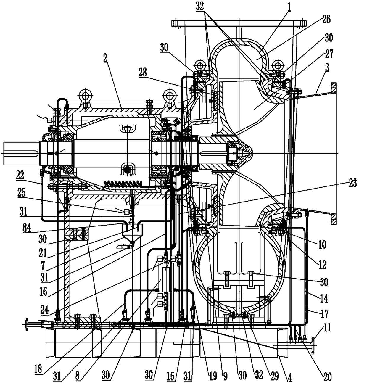
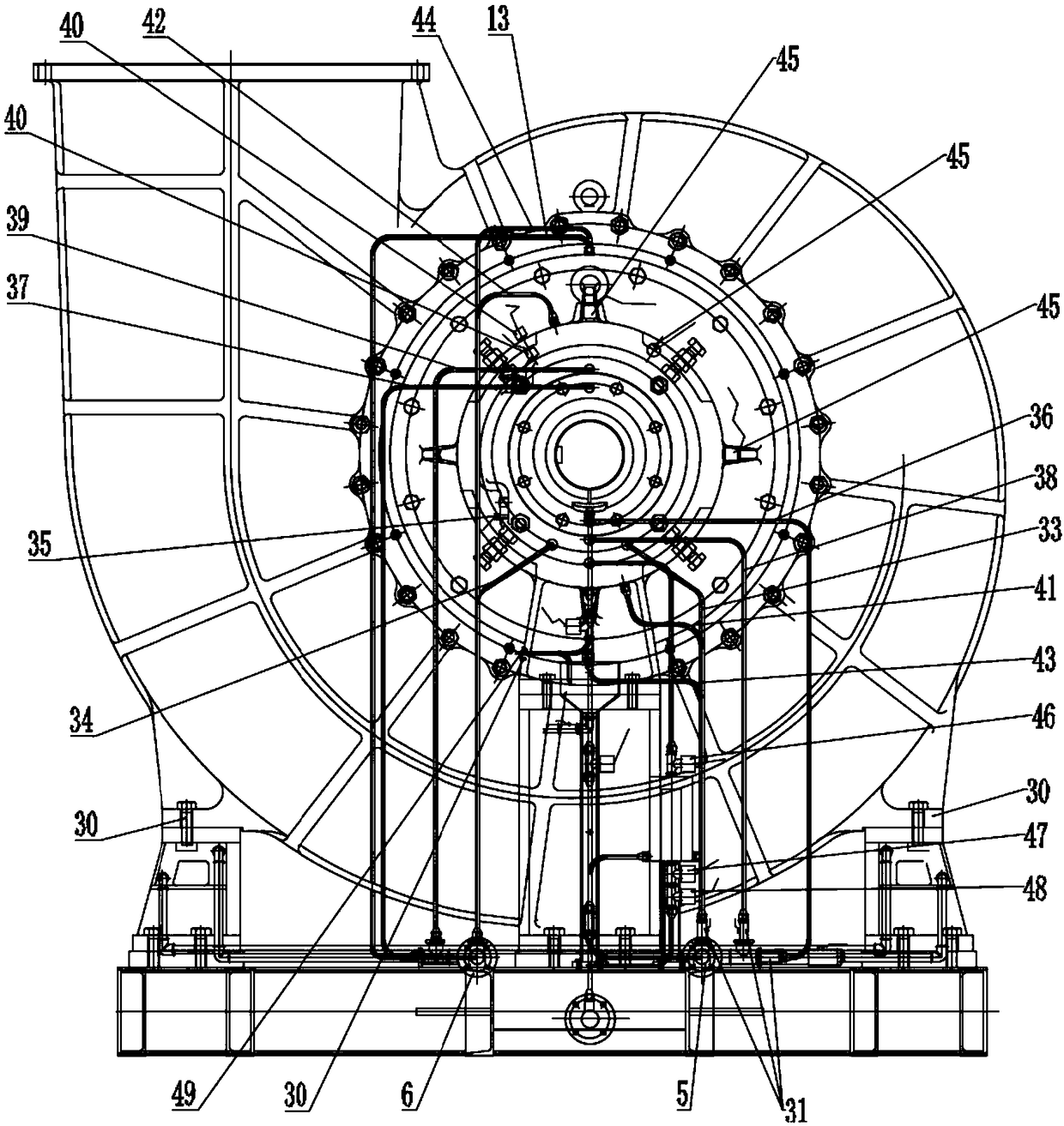
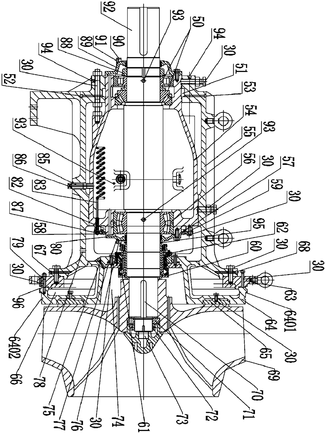
[0043] In the description of the present invention, it should be noted that the terms "center", "longitudinal", "transverse", "upper", "lower", "front", "rear", "left", "right", " The orientations or positional relationships indicated by "vertical", "horizontal", "top", "bottom", "inner", "outer", etc. are based on the orientation or positional relationships shown in the drawings, and are only for the convenience of describing the present invention and simplifying Describes, but does not indicate or imply that the device or element referred to must have a specific orientation, be constructed in a specific orientation, and operate in a specific orientation, and therefore should not be construed as limiting the invention. In addition, the terms "first", "second", and "third" are used for descriptive purposes only, and should not be construed as indicating or implying relative importance.

[0044] In the description of the present invention, it should be noted that unless otherwi...


PUM


Abstract

The invention provides an environment-friendly slurry circulating pump set. The environment-friendly slurry circulating pump set is provided with a front bearing cooling system, a rear bearing coolingsystem, a front pump cavity cooling system, a rear pump cavity cooling system, a lubricating oil cooling system, a mechanical seal cooling flushing system, a base cooling system, a pump set residualaxial force automatic balance system, a lubricating oil cooling system, a mechanical seal leak detection and residual discharging system, an oil chamber water inlet detection system, a lubricating oilleakage collecting system and a pump cavity leakage residual discharging system. All parts of the pump set can be heated or cooled according to the need, so that the pump set operates normally, safely and stably, the pump set is protected, the service life of the pump set is prolonged, the pump set can work under different temperature environments and working conditions, mediums of different temperatures can further be pumped and conveyed, diversified application is achieved, pumped and conveyed residuals, the leaked medium and leaked bearing lubricating oil of a slurry circulating pump can be recycled completely, and the cleanliness and sanitation of the environment are ensured.

Description

technical field [0001] The invention relates to a circulation pump, in particular to an environment-friendly slurry circulation pump set. Background technique [0002] The environmentally friendly slurry circulation pump group belongs to the single-stage single-suction horizontal centrifugal slurry pump, which is mainly used in the wet flue gas desulfurization system of thermal power coal-fired units, the alumina decomposition circulation system of aluminum plants and other slurry circulation systems. Wet desulfurization technology has high deflow efficiency and is the key application of deflow technology in national thermal power coal-fired units, while the decomposition of alumina is an important production process in aluminum plants. Environmentally friendly slurry circulating pumps are key equipment in wet flue gas desulfurization devices and alumina decomposition circulation systems. [0003] In the wet flue gas desulfurization system, the medium transported by the pum...

Claims


Application Information

Patent Timeline
Patent Type & Authority Applications(China)
IPC IPC(8): F04D7/04F04D7/06F04D29/58F04D15/00F04D29/66F04D29/06F04D29/00F04D29/10F04D29/70F04D29/62
CPCF04D7/04F04D7/06F04D15/00F04D15/0005F04D29/007F04D29/061F04D29/106F04D29/5886F04D29/628F04D29/669F04D29/708
Inventor 王泽兵江劲松王靖唐建迎赵彬罗先荣魏家楷罗洪滨蒋世宏
Owner GUANGZHOU XINHENG PUMP MFG
Why Eureka
Try Eureka