Heat dissipater device with heat-isolation layer

A technology of radiator and heat insulation layer, applied in the direction of heat exchanger type, indirect heat exchanger, heat transfer modification, etc., can solve the problems of slow water cooling process, low efficiency, easy temperature accumulation, etc., and achieve fast cooling speed. , Complete heat dissipation effect

Inactive Publication Date: 2018-09-04
边会婷
View PDF6 Cites 3 Cited by
  • Summary
  • Abstract
  • Description
  • Claims
  • Application Information

AI Technical Summary

Problems solved by technology

[0003] The existing water-cooled radiator absorbs heat through the incoming water. When the water returns to the water tank, the air cooling system cools the water in the water tank. After the water cools down, it passes into the water-cooled radiator to absorb heat again. Continuous circulation to complete the water cooling process, but this water cooling process is slow, if the water in the water tank is not completely cooled, the efficiency is not high, and its temperature is easy to accumulate

Method used


Image

  • Heat dissipater device with heat-isolation layer
  • Heat dissipater device with heat-isolation layer
  • Heat dissipater device with heat-isolation layer

Examples


Embodiment

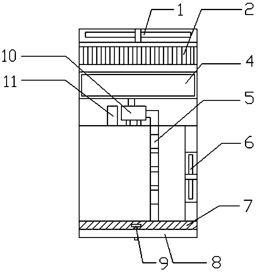
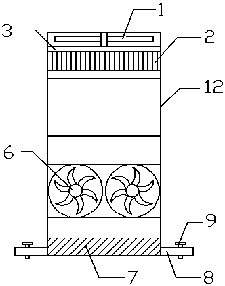
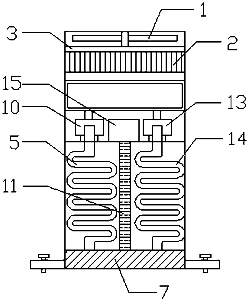
[0018] Example: such as Figure 1-3 As shown, it includes a water tank cooling fan 1, a fixed frame 3 is arranged under the water tank cooling fan 1, an insert radiator 2 is arranged under the fixed frame 3, and a water supply layer 12 is arranged under the insert radiator 2, The inside of the water supply layer 12 is provided with a copper water tank 4, a first small water pump 10 and a second small water pump 13 are arranged below the copper water tank 4, and a small water pump 10 and a second small water pump 13 are arranged between the first small water pump 10 and the second small water pump 13. There is a power source 15, a first serpentine pipe 5 is connected below the first small water pump 10, a second serpentine pipe 11 is arranged below the second small water pump 13, and the first serpentine pipe 5 is connected to the first serpentine pipe 5. The two serpentine tubes 14 are separated by a vacuum insulation panel 11. Two main cooling fans 6 are arranged on one side ...


PUM


Abstract

The invention discloses a heat dissipater device with a heat-isolation layer. The heat dissipater device with the heat-isolation layer comprises a water tank heat-dissipation fan, wherein a fixing frame is arranged below the water tank heat-dissipation fan; an insertion-sheet heat dissipater is arranged below the fixing frame; a water supply layer is arranged below the insertion-sheet heat dissipater; a molten copper tank is arranged in the water supply layer; a first small water pump and a second small water pump are arranged below the molten copper tank; a power supply is arranged between the first small water pump and the second small water pump; a first coiled pipe is connected below the first small water pump; a second coiled pipe is connected below the second small water pump; the first coiled pipe and the second coiled pipe are spaced through a vacuum heat-isolation plate; two main heat-dissipation fans are arranged at one side of each of the first coiled pipe and the second coiled pipe; and one end of each of the first coiled pipe and the second coiled pipe is connected with a water-cooling heat dissipater. The heat dissipater device with the heat-isolation layer is convenient to use, high in heat-dissipation speed, high in heat-dissipation effect, and suitable for being popularized and used.

Description

technical field [0001] The invention relates to a heat sink device with a heat insulating layer, and specifically belongs to the technical field of heat sinks. Background technique [0002] A device or instrument that transfers heat generated by machinery or other appliances in the course of work in a timely manner to avoid affecting its normal operation. Common radiators can be divided into air cooling, heat pipe radiator, liquid cooling, semiconductor refrigeration, compressor refrigeration and other types according to the heat dissipation method. The heat sink material refers to the specific material used for the heat sink. The thermal conductivity of each material is different, and the thermal conductivity is arranged from high to low, namely silver, copper, aluminum, and steel. However, it would be too expensive to use silver as a heat sink, so the best solution is to use copper. The heat dissipation method refers to the main way the heat sink dissipates heat. In ther...

Claims


Application Information

Patent Timeline
Patent Type & Authority Applications(China)
IPC IPC(8): F28D7/08F28F13/00
CPCF28D7/082F28F13/00
Inventor 边会婷
Owner 边会婷
Why Eureka
Try Eureka