Eureka AIR delivers breakthrough ideas for toughest innovation challenges, trusted by R&D personnel around the world.

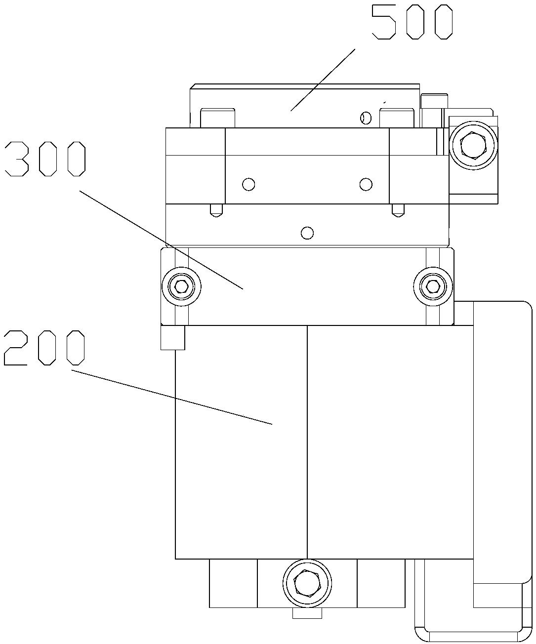
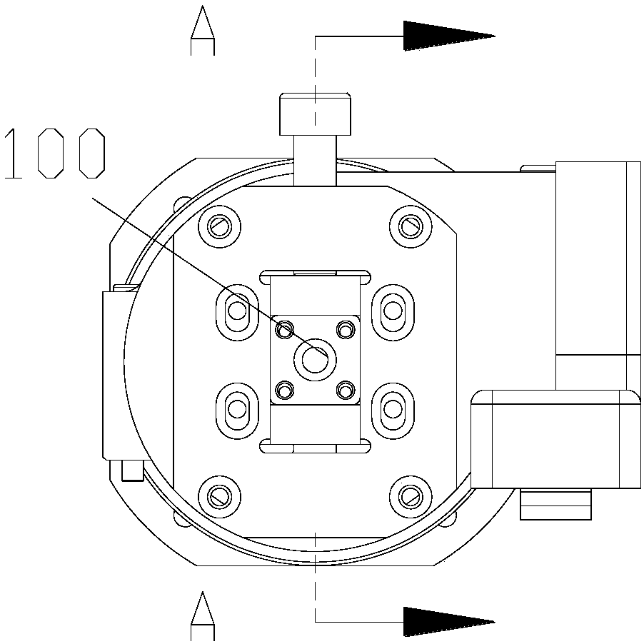
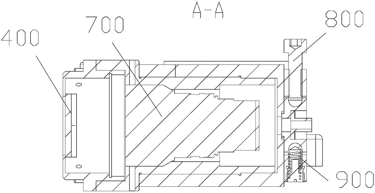
Linear light source and line scanning camera colinear adjusting device

A line-scan camera and adjustment device technology, applied in installation, optics, optical components, etc., can solve problems such as difficult alignment of camera sectors, high requirements for coaxiality, and difficulty in ensuring coaxiality, etc., to reduce vibration The risk of looseness, low processing difficulty, and the effect of ensuring coaxiality

Pending Publication Date: 2018-09-04
亿新(北京)科技有限公司
View PDF0 Cites 2 Cited by
  • Summary
  • Abstract
  • Description
  • Claims
  • Application Information

AI Technical Summary

Problems solved by technology

[0007] The disadvantages are: the focus handwheel, the focus lever and the cover of the focusing lens group are in clearance fit with each other, which increases the difficulty of processing. At the same time, it is difficult to guarantee the coaxiality. The equipment has high requirements on the coaxiality.
If the laser light entrance is not concentric with the condenser, the straightness of the straightness of the straightness of the straightness of the straightness of the straightness of the straightness of the straightness of the straightness of the straightness of the light source generated after the spot after the condenser is converged by the straightness generator will be affected.

Method used


Image

  • Linear light source and line scanning camera colinear adjusting device
  • Linear light source and line scanning camera colinear adjusting device
  • Linear light source and line scanning camera colinear adjusting device

Examples


Embodiment Construction

[0064] Embodiments of the present invention are described in detail below, and examples of the embodiments are shown in the drawings, wherein the same or similar reference numerals denote the same or similar elements or elements having the same or similar functions throughout. The embodiments described below by referring to the figures are exemplary and are intended to explain the present invention and should not be construed as limiting the present invention.

[0065] The invention provides a line-line light source and a line-scanning camera collinear adjustment device, which can adjust the relative position of the line-line light source and the line-scan camera, so as to meet the application of the line-scan camera in detection, such as locomotives and tracks on railways Detection, and gradually extended to tunnels, road surfaces, subways and other fields.

[0066] Such as Figures 1 to 14b As shown, the collinear adjustment device for a word-line light source and a line-sc...


PUM


Abstract

The invention provides a linear light source and line scanning camera colinear adjusting device, comprising a linear light source and a line-scan digital camera, wherein the linear light source comprises a fixed mounting plate, a light barrel main body locked on the fixed mounting plate by a locking screw, a laser inlet movably arranged at one side of the light barrel main body, and a light barrellens set shell; the light barrel main body and the light barrel lens set shell adjust the relative positions of a lens set and the laser inlet by a thread pair, a condensing lens set is arranged in the light barrel set shell, and the light barrel lens set shell is fixed on the light barrel main body by a light barrel lens set fixing ring; a linear light source generator mounting seat is arrangedat one side of the light barrel lens set shell, a linear light source generator is arranged on the linear light source generator mounting seat, and a linear light source generator adjusting module isarranged at one side of the linear light source generator. According to the invention, a section where the light source is located can be rapidly and accurately superposed with a section where a line-scan digital camera chip is located.

Description

technical field [0001] The invention relates to the technical field of line-scan cameras, in particular to a collinear adjustment device for a line light source and a line-scan camera. Background technique [0002] A typical field of application for line scan cameras is the detection of continuous materials such as metals, plastics, paper and fibers. The detected object usually moves at a constant speed, and one or more cameras are used to continuously scan it line by line to achieve uniform detection of its entire surface. When detecting high-speed moving objects, line scan cameras have obvious advantages. When using a line scan camera, a special light source needs to be provided. The light source is a linear light source, and the light from the fan surface comes out from the light outlet. When the fan surface where the light source is located and the line array camera chip (the camera chip is the core component of camera imaging, mainly divided into two types of CCD and...

Claims


Application Information

Patent Timeline
Patent Type & Authority Applications(China)
IPC IPC(8): G02B7/00
CPCG02B7/00G02B7/003
Inventor 张琳琳
Owner 亿新(北京)科技有限公司
Why Eureka
Eureka Blog
Learn More