Supercharge Your Innovation With Domain-Expert AI Agents!

Non-polar cable insulation and sheath surface marking device and marking process thereof

A cable insulation, non-polar technology, applied in the direction of marking conductors/cables, cable/conductor manufacturing, circuits, etc., can solve the problems of difficult printing and marking, poor adhesion, trouble, etc., to increase versatility and improve qualification. efficiency, improve efficiency

Inactive Publication Date: 2018-09-04
ANHUI HUAYU CABLE GRP
View PDF4 Cites 1 Cited by
  • Summary
  • Abstract
  • Description
  • Claims
  • Application Information

AI Technical Summary

Problems solved by technology

[0002] The existing inkjet marking technology is to use an inkjet printer to print on the surface of the cable insulation or sheath. The working principle of the inkjet printer is that when ink flows out of the nozzle, the power supply circuit charges the ink flowing out. The ink droplets in the ink are charged, and the charged ink droplets pass through the deflection magnetic field formed by the deflection motor. Under the action of the magnetic field, the corresponding deflection will occur. After the deflection, the ink droplets will drop to the surface of the insulation or sheath and fall on the insulation or sheath. The ink drop on the surface of the sleeve finally forms an ink dot, that is, the marking of an ink dot is completed. Since the ink materials used in the inkjet printer are all polar materials, the polar ink is attached to the surface of the non-polar insulating material. The focus is very poor, so the existing inkjet marking technology is not only difficult to print and mark on the surface of cable insulation or sheath made of non-polar materials such as polyethylene, cross-linked polyethylene, silicone rubber, and fluoroplastics, Even after barely inkjet printing, it can be easily wiped off
[0003] In actual production, these non-polar material insulated core wires printed with inkjet marking technology appear to be clearly marked in the wiring process. It will cause most of the surface markings of the insulated core wires to be wiped. Therefore, most of the computer cables, control cables, and marine cables that use polyethylene, cross-linked polyethylene, and fluoroplastics as insulation materials, as well as silicone rubber as insulation and The actual production and use of special cables with sheath materials have caused great troubles, and at the same time, most of the above-mentioned products cannot pass the relevant national sampling inspections and the printing and abrasion resistance tests on the surface of insulated cores submitted by customers for inspection

Method used


Image

  • Non-polar cable insulation and sheath surface marking device and marking process thereof

Examples


Embodiment Construction

[0021] In order to make the technical means, creative features, goals and effects achieved by the present invention easy to understand, the present invention will be further elaborated below.

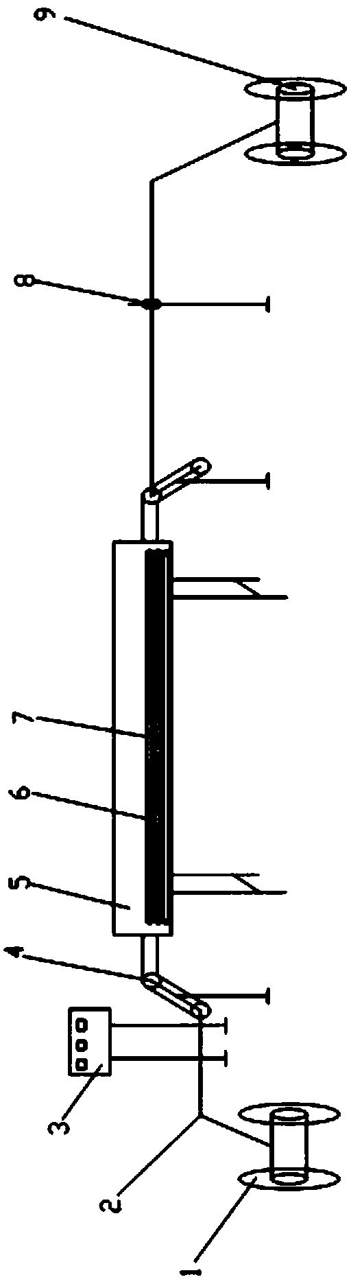
[0022] Such as figure 1 As shown, the insulated wire core 2 is arranged on the pay-off device 1, and a control panel 3 that can set corresponding process parameters according to the material is arranged beside the pay-off device 1, and a control panel 3 is arranged beside the control panel 3 A wire storage device 4 composed of four tension guide wheels, a heat preservation oven 5 for heat preservation is arranged beside the wire storage device 4, and a heating tube 6 for heating is built in the heat preservation oven 5. The middle part of 5 is equipped with thermocouple temperature measuring device 7, described thermocouple temperature measuring device 7 cooperates with control panel 3 and displays the temperature on the control panel 3 in real time, and described insulated wire core 2 ...


PUM

PropertyMeasurementUnit
lengthaaaaaaaaaa
widthaaaaaaaaaa
heightaaaaaaaaaa

Abstract

The invention belongs to the cable field and relates to a non-polar cable insulation and sheath surface marking device and a marking process thereof. The device comprises a pay-off device and a printing and code printing machine matched with the pay-off device; an insulation wire core is arranged on the pay-off device; a control panel for setting corresponding process parameters according to materials is arranged beside the pay-off device; a wire storage device is arranged beside the control panel; a thermal insulation drying box is arranged beside the wire storage device; heating tubes for heating are arranged in the thermal insulation drying box; a thermocouple temperature measuring device is installed at the middle of the thermal insulation drying box; and the insulation wire core is heated by the thermal insulation drying box and printed by the printing and code printing machine, and then is collected on a wire coil through an active take-up rack for taking up the wire. The markingprocess of the device includes the following steps that: (1) heating tubes are set; (2) the size of the thermal insulation drying box is set; and (3) process parameters are set. Marks printed by thenon-polar marking device of the invention are resistant to abrasion and have little possibility of being worn compared with marks printed by polar marking devices; and the non-polar marking device ofthe invention can improve the pass rate of cable marking.

Description

technical field [0001] The invention relates to the field of cables, in particular to a non-polar cable insulation and sheath surface marking device and a marking process thereof. Background technique [0002] The existing inkjet marking technology is to use an inkjet printer to print on the surface of the cable insulation or sheath. The working principle of the inkjet printer is that when ink flows out of the nozzle, the power supply circuit charges the ink flowing out. The ink droplets in the ink are charged, and the charged ink droplets pass through the deflection magnetic field formed by the deflection motor. Under the action of the magnetic field, the corresponding deflection will occur. After the deflection, the ink droplets will drop to the surface of the insulation or sheath and fall on the insulation or sheath. The ink drop on the surface of the sleeve finally forms an ink dot, that is, the marking of an ink dot is completed. Since the ink materials used in the inkj...

Claims


Application Information

Patent Timeline
Patent Type & Authority Applications(China)
IPC IPC(8): H01B13/34
CPCH01B13/345
Inventor 水利飞叶明竹邓九旺叶宇叶常青肖尚兵赵家浪王根生
Owner ANHUI HUAYU CABLE GRP
Features
  • R&D
  • Intellectual Property
  • Life Sciences
  • Materials
  • Tech Scout
  • Unparalleled Data Quality
  • Higher Quality Content
  • 60% Fewer Hallucinations
Learn More