Antenna structure and communication terminal

An antenna structure and communication terminal technology, which is applied in the direction of antenna grounding switch structure connection, antenna, antenna parts, etc., can solve the problems of communication terminal NFC performance limitation, magnetic flux Φ limitation, etc.

Active Publication Date: 2018-09-04
HUAWEI TECH CO LTD
View PDF12 Cites 6 Cited by
  • Summary
  • Abstract
  • Description
  • Claims
  • Application Information

AI Technical Summary

Problems solved by technology

because figure 1 The radiator of the NFC antenna is a part of the radiator of the non-NFC antenna, so the length of the radiator of the NFC antenn

Method used


Image

  • Antenna structure and communication terminal
  • Antenna structure and communication terminal
  • Antenna structure and communication terminal

Examples


Embodiment Construction

[0040] In order to enable those skilled in the art to better understand the solution of the present application, the present application will be further described in detail below in conjunction with the drawings and specific implementation methods. Apparently, the described embodiments are only some of the embodiments of this application, not all of them.

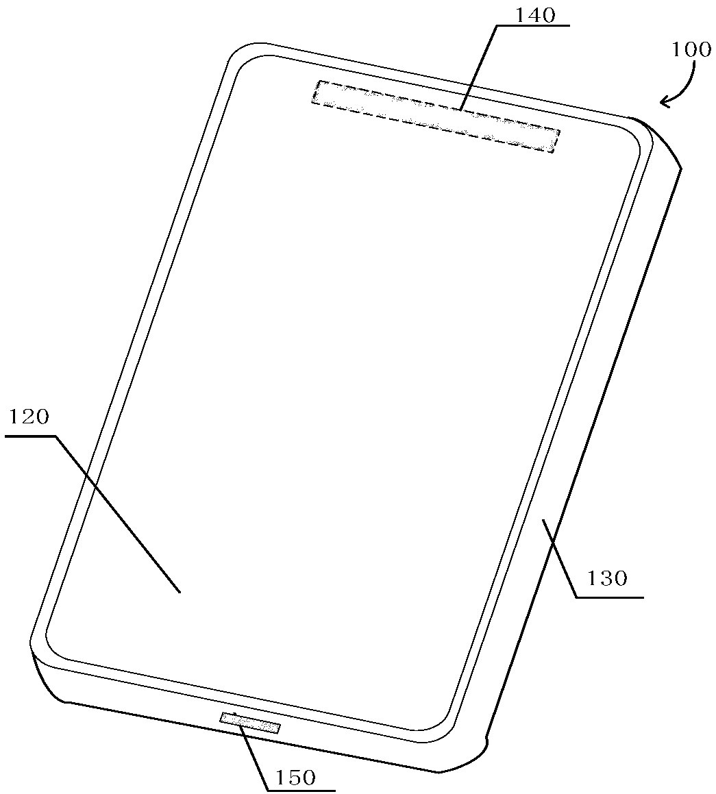
[0041] Please refer to figure 2, is a schematic diagram of an external structure of a communication terminal provided by an embodiment of the present invention. The communication terminals involved in the present invention include mobile phones, tablet computers, laptop computers, routers, home gateways, set-top boxes, vehicle-mounted devices, and the like. The "communication terminal" that appears as a term in the full text can be replaced by terms such as terminal products, electronic equipment, communication products, handheld terminals, and portable terminals.

[0042] Exemplarily, the communication terminal 100 has ...


PUM


Abstract

Disclosed is an antenna structure, applied in a communication terminal. The communication terminal comprises a metal bezel. The metal bezel comprises at least one gap. The antenna structure comprises:a near-field communication (NFC) antenna and a non-NFC antenna. The NFC antenna comprises an NFC radiator, a first filtering unit, and an NFC circuit. The non-NFC antenna comprises a non-NFC radiator, a second filtering unit, and a non-NFC circuit. The NFC radiator and the non-NFC radiator are formed of the metal bezel of the communication terminal. The non-NFC radiator is totally within the NFCradiator. The NFC circuit is coupled to the NFC radiator by means of the first filtering unit. The non-NFC circuit is coupled to the non-NFC radiator by means of the second filtering unit. The first filtering unit is used for filtering out a non-NFC signal generated by the non-NFC circuit. The second filtering unit is used for filtering out an NFC signal generated by the NFC circuit.

Description

technical field [0001] The present application relates to the field of wireless communication antennas, in particular to an antenna structure and a communication terminal. Background technique [0002] In mobile communication, it usually includes three important components, namely communication terminal, base station and wireless network. Taking a phone call as an example, when a user speaks using a communication terminal, the communication terminal of the sender converts the voice into radio waves, and after receiving the radio waves, the base station near the communication terminal of the sender transmits the radio waves to the receiver through the wireless network. The base station near the receiving party, and then the base station near the receiving party transmits radio waves to the communication terminal of the receiving party, and the communication terminal converts the radio wave into voice and transmits it to the user of the receiving party. In this process, the a...

Claims


Application Information

Patent Timeline
IPC IPC(8): H01Q23/00H01Q1/36H01Q1/44H01Q1/50H01Q1/24
CPCH01Q1/242H01Q1/36H01Q1/44H01Q1/50H01Q23/00H01Q1/48H01Q1/243H04B5/0075H01Q5/335H01Q1/521
Inventor 朱伟王毅李堃呼延思雷张云路宝卢士强
Owner HUAWEI TECH CO LTD
Why Eureka
Try Eureka