Disk punching device

A technology of punching device and disc, applied in metal processing and other directions, can solve the problems of inability to process discs with the same indexed holes, incapability of mass production, low work efficiency, etc. The effect of production efficiency

Inactive Publication Date: 2018-09-07
宁波鑫神泽汽车零部件有限公司
View PDF0 Cites 3 Cited by
  • Summary
  • Abstract
  • Description
  • Claims
  • Application Information

AI Technical Summary

Problems solved by technology

[0003] The purpose of the present invention is to provide a disc punching device to solve the problems of the prior art that cannot be produced

Method used


Image

  • Disk punching device

Examples


Embodiment 1

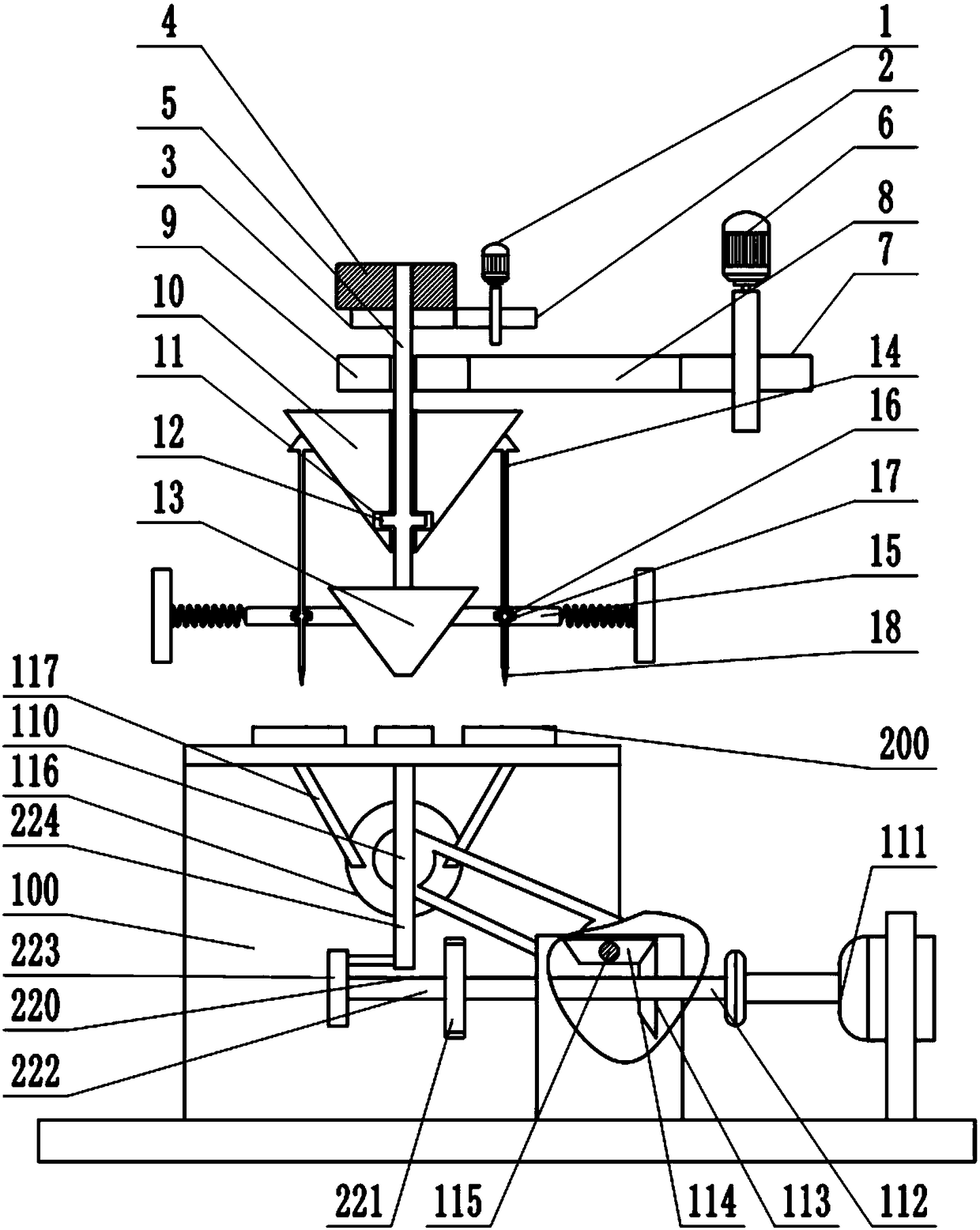
[0021] Such as figure 1 As shown, the disc drilling device includes a frame 4, a driving mechanism, a workbench and a drilling mechanism. The drilling mechanism includes a first motor 1, and the output shaft of the first motor 1 is connected with a driving gear 2, and one side of the driving gear 2 A driven gear 3 meshed with the driving gear 2 is connected, the driven gear 3 is provided with an internal thread, the internal thread hole of the driven gear 3 is provided with a screw 5 matching the internal thread, and the frame 4 is provided with a chute , the screw rod 5 is provided with a bump matching the chute, the screw rod 5 is covered with a conical rotor 10, the conical rotor 10 is driven by a driving mechanism, the driving mechanism includes a second motor 6, and the output shaft of the second motor 6 is connected to There is a driving pulley 7, the driving pulley 7 is connected with a driven pulley 9 through a belt 8, the driven pulley 9 is connected with a driven sha...

Embodiment 2

[0026] The difference between this embodiment and the first embodiment is that the output shaft of the second motor 6 is connected to a gear shaft, and the inner hole of the driving pulley 7 is provided with internal teeth meshing with the gear shaft. When the screw 5 drives the conical rotor 10 to move up and down, it will cause the belt 8 to deviate, which will easily cause the problem of unstable transmission. Through the meshing relationship between the gear 221 shaft and the internal teeth of the driving pulley 7, the driving pulley 7 will Automatically balance the position deviation of the belt 8, thereby bringing stable transmission.

Embodiment 3

[0028] The difference between this embodiment and the first or second embodiment is that: the driven shaft is connected with a telescopic rod, and the lower end of the telescopic rod is fixedly connected with the conical rotor 10 . When the screw rod 5 drives the conical rotor 10 to move up and down, the telescopic rod can ensure that the transmission of the belt 8 is not affected by the movement of the conical rotor 10 by stretching and shortening.


PUM


Abstract

The invention belongs to the technical field of disk type component drilling tools and particularly discloses a disk punching device. The disk punching device comprises a rack, a drive mechanism, a clamping device, a workbench and a drilling mechanism. The drilling mechanism comprises a first motor, a drive gear and a driven gear. The driven gear is provided with an inner threaded hole, the innerthreaded hole of the driven gear is provided with a threaded rod, the threaded rod is sleeved with a tapered rotor, and the tapered rotor is internally provided with a first groove. The threaded rod is provided with a first protrusion, the lower end of the threaded rod is connected with a tapered column, a plurality of tapered drill rods are arranged on the circumferential side of the tapered rotor, the lower portions of the tapered drill rods are sleeved with drill bushings, one sides of the drilling bushings are connected with springs fixed to the rack, the other sides of the drilling bushings are in sliding connection with the side wall of the tapered column, the drill bushings are internally provided with second grooves, the tapered drill rods are provided with second protrusions, andthe lower ends of the tapered drill rods are connected with drill bits. By adopting the technical scheme, the working efficiency can be improved, and the problem that disks with different diameters but with same index holes cannot be machined is solved.

Description

technical field [0001] The invention belongs to the technical field of drilling tools for disc parts, in particular to a disc drilling device. Background technique [0002] Disc-like parts are very common in the mechanical manufacturing process. Due to the needs of process design, sometimes it is necessary to drill equal parts on the circular end surface of the outer circumference of the disc. At this stage, the general practice of the staff is to clamp the workpiece on the dividing head, use the dividing head to divide and mark the position of the workpiece to be drilled, and finally use the drill bit to drill the hole, or directly install the dividing head on the Set the position on the drilling machine, each time a hole is punched, then shake the dividing head to the position of the next hole and continue drilling until the entire hole is drilled. There are the following problems in adopting these punching methods: 1. It is necessary to pre-divide the bisector or shake t...

Claims


Application Information

Patent Timeline
IPC IPC(8): B26F1/16B26D5/06B26D5/08B26D7/02B26D7/20B26D7/26
CPCB26F1/16B26D5/06B26D5/083B26D5/086B26D7/025B26D7/20B26D7/2614B26D7/2628
Inventor 王健
Owner 宁波鑫神泽汽车零部件有限公司
Why Eureka
Try Eureka