Connecting method and device of auxiliary framework seats and bearing saddles of wagon self-steering bogie

A technology for railway freight cars and load-bearing saddles, which is applied to bogies, railway car body components, transportation and packaging, etc., can solve the problems of large assembly workload, eliminate welding residual stress, hidden dangers in vehicle operation, and reduce manufacturing accuracy requirements. , Improve system reliability and reduce maintenance costs

Pending Publication Date: 2018-09-07
株洲市求拙机械制造有限公司
View PDF10 Cites 3 Cited by
  • Summary
  • Abstract
  • Description
  • Claims
  • Application Information

AI Technical Summary

Problems solved by technology

Therefore, the main disadvantages of this assembly method are: 1) When the bearing saddle 3 and the sub-frame 5 are assembled, the positioning must be completed on the special tooling, and the bearing saddle wedge 4 is used for on-site matching and welding to complete their relative positional relationship Determination of the determination, the assembly workload is large, resulting in an increase in manufacturing and maintenance costs, which is not conducive to mass promotion
2) After the welding method is used for welding, the welding residual stress cannot be easily eliminated, and the sub-frame 5, the bearing saddle wedge 4 and the bearing saddle 3 are all unsprung masses, which are easy to withstand the high-frequency disturbance transmitted by the line. Generate fatigue cracks, affect the reliability of the guiding mechanism, and bring safety hazards to vehicle operation
This method has a certain effect on improving the uniform stress of the bearing. However, due to the unbalanced load on the bearing caused by the elastic force of the leaf spring, it cannot fundamentally solve the problem of the uniform stress of the bearing in the vertical direction.
Moreover, due to the use of adjusting shims in the horizontal direction, the interchangeability problem has not been effectively solved.
At the same time, there are relatively many connection and fastening links, especially the connection links that transmit the guiding force, and the problem of connection reliability has not been completely resolved.
[0009] The patent number is "CN203651975 U", which discloses a "sub-frame bogie with split structure of bearing saddle", adding elastic pads of bearing saddle between the sub-frame and the bearing saddle, which can solve the problem of uniform vertical load transmission of the bearings , but due to the elasticity of the horizontal plane, it will affect the transmission of the guiding force and reduce its self-guiding effect
[0010] Therefore, although the above-mentioned patents all relate to the self-guiding of railway freight car bogies, and have also proposed some structural improvements, they have not fundamentally changed the existing problems of self-guiding, so further improvements are still needed

Method used


Image

  • Connecting method and device of auxiliary framework seats and bearing saddles of wagon self-steering bogie
  • Connecting method and device of auxiliary framework seats and bearing saddles of wagon self-steering bogie
  • Connecting method and device of auxiliary framework seats and bearing saddles of wagon self-steering bogie

Examples


Embodiment 1

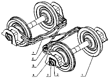
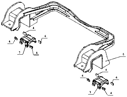
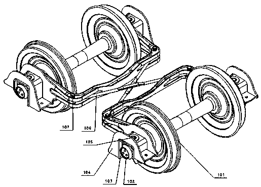
[0036] by attaching Figure 2-6 It can be seen that the present invention relates to a coupling device between a sub-frame seat and a bearing saddle of a self-steering bogie of a railway freight car, including a wheel set, a rolling bearing device, a bearing saddle, a sub-frame, and a cross-connecting rod; wherein, the rolling bearing device is assembled on the wheel set On the journal, the bearing saddle is seated on the outer ring of the rolling bearing device through its arc-shaped surface seat, and the sub-frame and the cross-connecting rod are connected by cylindrical pins. .

[0037] There are two horizontal bearing planes at both ends of the sub-frame; two spherical bosses are symmetrically distributed along the longitudinal direction (vehicle running direction) and transverse direction (parallel to the axis of the axle) on the top of the bearing saddle. At the same time, the longitudinal and transverse centerlines of the bearing saddle top are The point of intersectio...

Embodiment 2

[0045] The structure of the second embodiment is the same as the basic principle of the first embodiment, except that the spherical boss is fixed on the bearing bottom surface of the sub-frame, and the top surface of the bearing saddle is a plane at this time.

[0046] Further, the vertical shaft is fixed on the bearing bottom surface of the sub-frame, and the bearing saddle top surface has a cylindrical hole for fixing the outer ring of the joint bearing.

[0047] Further, the spherical boss on the same top surface of the bearing saddle (or the same bearing surface of the sub-frame) is a cylindrical surface whose axis is located in the vertical symmetry plane of the arc surface of the bearing saddle (vehicle running direction).


PUM


Abstract

The invention provides a connecting method and device of auxiliary framework seats and bearing saddles of a wagon self-steering bogie. The device comprises wheel sets, rolling bearing devices, the bearing saddles, auxiliary frameworks and crossed connecting rods. The rolling bearing devices are assembled on shaft necks of the wheel sets, the bearing saddles are located on the outer rings of the rolling bearing devices through arc-shaped faces of the bearing saddles, and the auxiliary frameworks and the crossed connecting rods are connected through cylindrical pins. The method is characterizedin that each auxiliary framework is located on the two corresponding bearing saddles and connected with the bearing saddles through knuckle bearings; the auxiliary frameworks receive the vertical loadtransmitted by side frames of the bogie, and then the vertical load is evenly transmitted to the rolling bearing devices through the bearing saddles; and the bearing saddles receive wheel guide forcetransmitted from the rolling bearing devices, the wheel guide force is quasi-rigidly transmitted to the auxiliary frameworks through the knuckle bearings, and then the wheel guide force is transmitted to another wheel set through the crossed connecting rods and the like.

Description

technical field [0001] The invention relates to a walking method and device for railway freight cars, in particular to a self-guiding method and a bogie for a railway freight car bogie, in particular to a self-guiding method and a self-guiding bogie for a three-piece self-guiding bogie. The utility model is mainly used for steering-guided traction in the running process of railway freight cars, and belongs to the technical field of railway freight car bogie guides. Background technique [0002] The self-guiding radial bogie for railway wagons invented by Mr. Scheffel, a South African railway engineer, not only has excellent curve passing performance, but also has good straight line stability. Therefore, some curves in Africa and Southeast Asia have more curves and the curve radius is smaller Widely used on narrow gauge and meter gauge lines. [0003] At present, the self-steering bogies widely used in railway freight cars are based on the improved design of the traditional ...

Claims


Application Information

Patent Timeline
Patent Type & Authority Applications(China)
IPC IPC(8): B61F5/50B61F5/52
CPCB61F5/50B61F5/52
Inventor 李国曾庆祎刘兰英马佳雄周旭陈亮
Owner 株洲市求拙机械制造有限公司
Why Eureka
Try Eureka