Cam box structure of material transferring mechanism for battery shell stamping

A technology of material shifting mechanism and battery shell, which is applied in the direction of cams, mechanical equipment, and components with teeth, etc., can solve the problems of large volume, high processing cost, and complex structure, and achieve small volume, low processing cost, and optimized structure Effect

Pending Publication Date: 2018-09-07
无锡市金杨新材料股份有限公司
View PDF0 Cites 2 Cited by
  • Summary
  • Abstract
  • Description
  • Claims
  • Application Information

AI Technical Summary

Problems solved by technology

[0003] The object of the present invention is to address the above problems, to provide a cam box structure of a material transfer mechanism for battery case stamping, so as to solve the problems of large volume, complex structure and high processing cost of the existing cam box structure of a material transfer mechanism for battery case stamping

Method used


Image

  • Cam box structure of material transferring mechanism for battery shell stamping
  • Cam box structure of material transferring mechanism for battery shell stamping
  • Cam box structure of material transferring mechanism for battery shell stamping

Examples


Embodiment Construction

[0016] The technical solutions of the present invention will be further described below in conjunction with the accompanying drawings and through specific implementation methods. It should be understood that the embodiments described here are only used to explain the present invention, but not to limit the present invention.

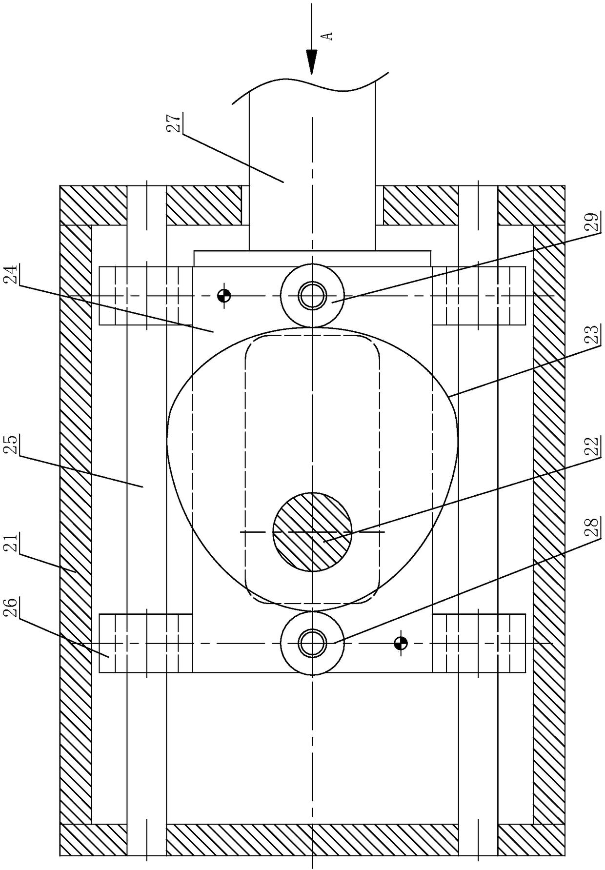
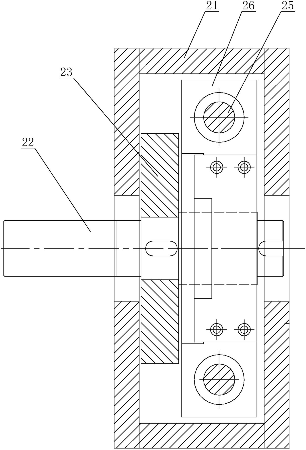
[0017] Please refer to figure 2 and image 3 as shown, figure 2 It is a top view of a cam box structure of a material transfer mechanism for battery case stamping; image 3 yes figure 2 The A-direction diagram of a battery case stamping material transfer mechanism shown.

[0018] In this embodiment, a cam box structure of a material transfer mechanism for battery case stamping includes a box body 21, a drive shaft 22 is rotatably connected to the box body 21 through a support bearing, and a drive shaft 22 is fixedly connected to the drive shaft 22. A cam 23 with a disk-shaped structure, the outer edge of the cam 23 is a curved profile, and the ca...


PUM


Abstract

The invention discloses a cam box structure for a material transferring mechanism for battery shell stamping. The cam box structure comprises a box body, a drive shaft is rotatably connected to the box body, and a cam with a disc-shaped structure is fixedly connected to the drive shaft; the outer edge of the cam is a curved contour, the cam is eccentrically arranged on the drive shaft, and the eccentricity distance is equal to the step distance of a progressive die; the cam is horizontally arranged in a box body, a sliding connection plate is slidably connected in the box body, the sliding connecting plate is horizontally arranged, and the sliding connecting plate is located at the lower part of the cam; a first bearing and a second bearing are arranged on the positions, on both sides of the cam, on the upper end surface of the sliding connecting plate; and when in operation, the curved contour of the cam meshes with one of the first bearing and the second bearing. The cam box structure has the characteristics of small volume and simple structure, the cam box adopting the cam box structure can realize transmission of power between a spindle of a punch press and the cam box only bya vertically arranged transmission shaft, and the structure is greatly optimized.

Description

technical field [0001] The invention relates to the field of stamping equipment, in particular to a cam box structure of a material transfer mechanism for stamping a battery case. Background technique [0002] At present, in the continuous punching production process of battery cases using progressive dies, the progressive feeding between adjacent stations is mostly realized through the material transfer mechanism. The motion is converted into linear reciprocating motion, however, the cam box structure of the existing material transfer mechanism for battery case punching is as follows: figure 1 As shown, the cam box structure of this kind has a large volume, and the cam 11 is difficult to process and takes a long time. It needs to be milled out on its circumferential surface as a whole. Its camshaft 12 is parallel to the slide shaft 13, both of which are arranged horizontally, and the main shaft of the punch press is above the punch press. Therefore, a vertically arranged v...

Claims


Application Information

Patent Timeline
Patent Type & Authority Applications(China)
IPC IPC(8): F16H25/14F16H57/023F16H53/02B21D22/02B21D43/00
CPCF16H25/14B21D22/02B21D43/00F16H53/02F16H57/023F16H2057/02069F16H2057/02086
Inventor 杨建林潘惠荣
Owner 无锡市金杨新材料股份有限公司
Why Eureka
Try Eureka