Shielded coil module and preparation method thereof

A technology for shielding coils and modules, applied in shielded loop antennas, antennas, antenna parts and other directions, can solve the problems of affecting the working performance of electronic equipment, affecting the shielding effect, low integration efficiency, etc. The effect of good magnetic isolation and high integration

Inactive Publication Date: 2018-09-07
SHANGHAI LINEPRINTING MATERIALS CO LTD
View PDF0 Cites 2 Cited by
  • Summary
  • Abstract
  • Description
  • Claims
  • Application Information

AI Technical Summary

Problems solved by technology

In the traditional preparation method, the thickness of the insulating layer between the coil and the traditional shielding material is large, and the integration efficiency is low, especially the shielding layer will inevitably affect the shielding effect, the working temperature will rise, and finally affect the working performance of the electronic equipment

Method used


Image

  • Shielded coil module and preparation method thereof
  • Shielded coil module and preparation method thereof
  • Shielded coil module and preparation method thereof

Examples


Embodiment 1

[0028] Embodiment 1 (NFC module):

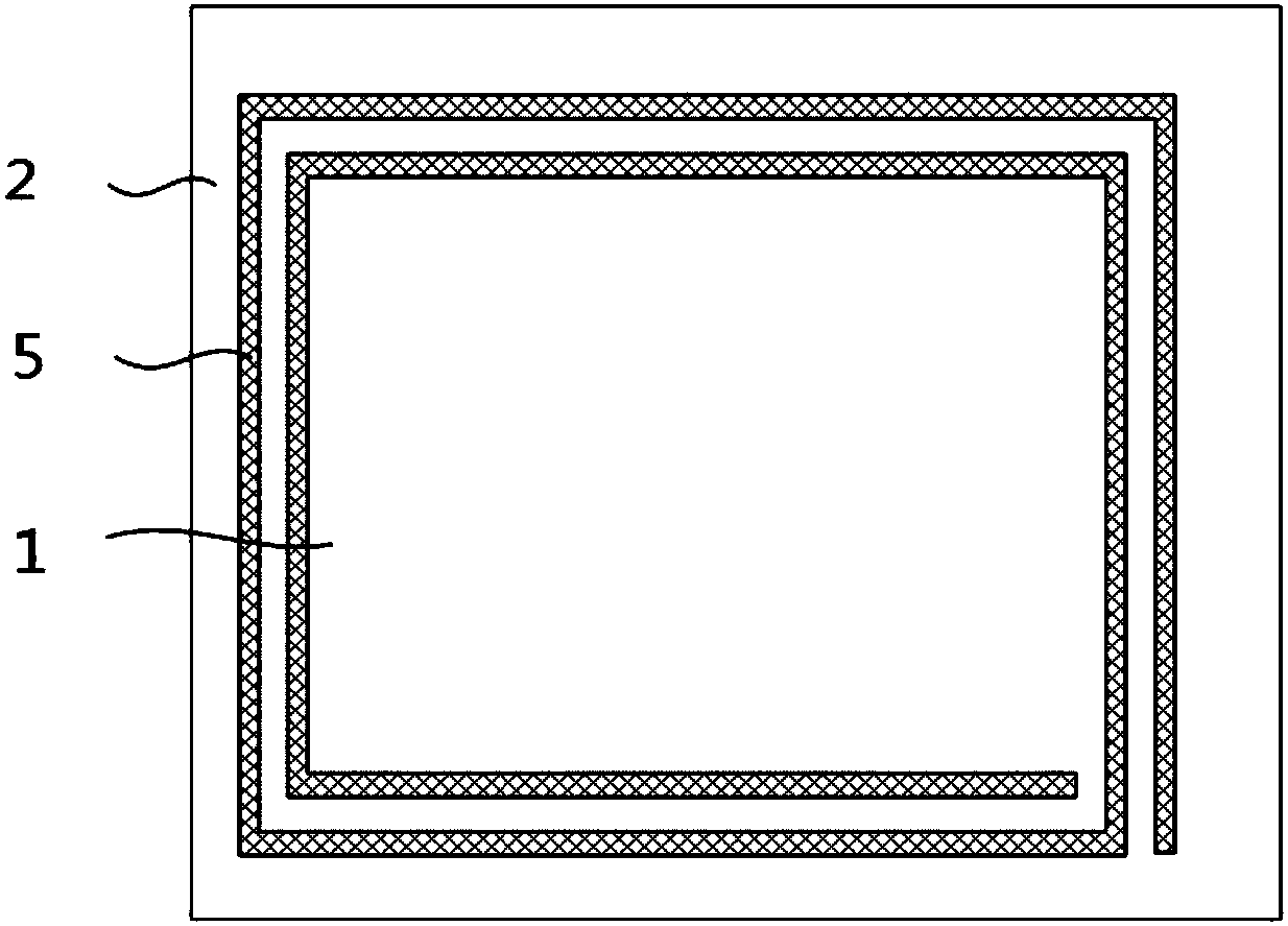
[0029] Such as figure 1 As shown, the present invention provides a shielding coil module 1. A shielding coil module 1 includes: a coil 5 formed on the upper surface of the base material 2, an insulating layer 10 formed on the upper surface of the coil 5 The shielding material layer 11 formed on the upper surface of the insulating layer 10 and the heat dissipation layer 13 formed on the upper surface of the shielding material layer 11 are placed on the battery metal plate 3; the manufacturing method includes the following steps:

[0030] A. A substrate 2 is provided, and a coil 5 is formed on the surface of the substrate 2;

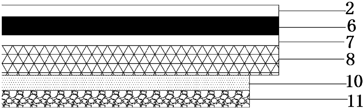
[0031] Specifically, the substrate 2 is a PI single-sided adhesive substrate. An ink layer 12 is formed on the adhesive-free side of the substrate 2, and the ink layer 6 is obtained on the surface of the ink layer 12 through a printing process to form a micro-conductive layer 7 by light source irradiation. A conductiv...

Embodiment 2

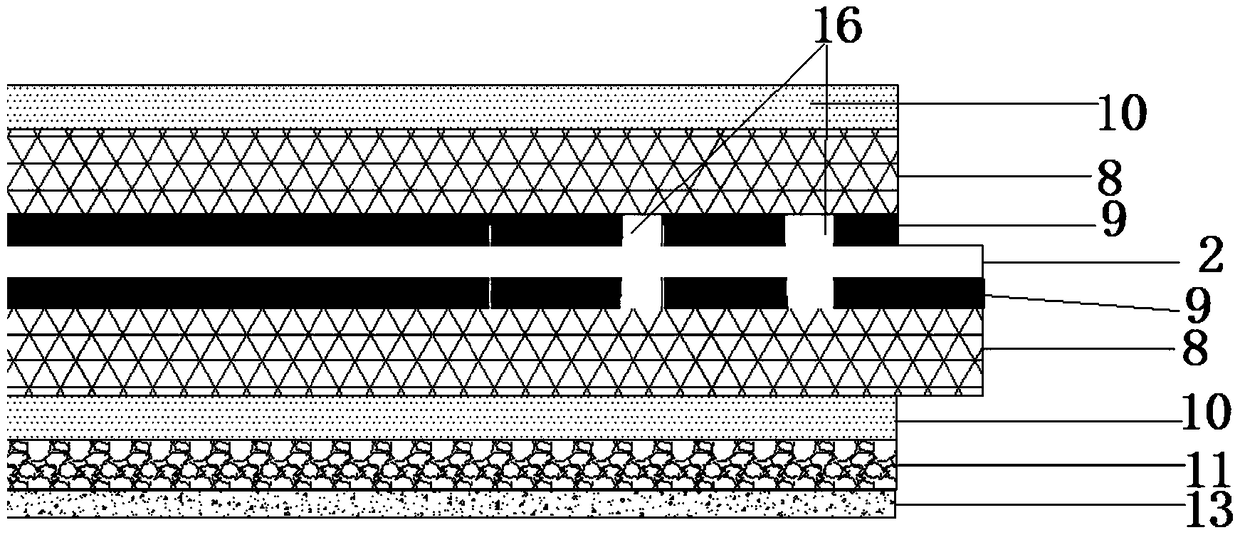
[0038] Such as image 3 Shown, preparation method of the present invention comprises the following steps at least:

[0039] A. A substrate 2 is provided, and a coil 5 is formed on the surface of the substrate 2 .

[0040] Specifically, the substrate 2 is an EMI absorbing material or a PI substrate. Such as figure 2 As shown, an ink layer 12 is formed on both sides of the substrate 2, and the coil catalytic ink layer 9 is obtained on the surface of the ink layer 12 by screen printing or coating process. Such as image 3 As shown, the electrolytic deposition method is used to form the conductive metal layer 8 on the surface of the catalytic ink layer 9 . Such as Figure 4 As shown, the coil 5 is formed.

[0041] B, forming an insulating layer 10 on the surface of the coil 5;

[0042] Specifically, the insulating layer 10 is formed by screen printing technology or coating technology, and the insulating layer 10 is located on the area of ​​the coil 5. The thickness of the ...

Embodiment 3

[0047] Embodiment 3 (NFC+WPC)

[0048] Such as Figure 4 Shown, the present invention provides a kind of preparation method of shielded coil module, and described preparation method comprises the following steps at least:

[0049] A. A substrate 2 is provided, and a coil 5 is formed on the surface of the substrate 2 .

[0050] Specifically, the substrate 2 is an EMI absorbing material or a PI substrate. Such as figure 2 As shown, an ink layer 12 is formed on both sides of the substrate 2, and the coil catalytic ink layer 9 is obtained on the surface of the ink layer 12 by screen printing or coating process. Such as image 3 As shown, the electrolytic deposition method is used to form the conductive metal layer 8 on the surface of the catalytic ink layer 9 . Such as Figure 4 As shown, the coil 5 is formed.

[0051] B, forming an insulating layer 10 on the surface of the coil 5;

[0052] Specifically, the insulating layer 10 is formed by screen printing technology or coa...


PUM


Abstract

The invention discloses a shielded coil module and a preparation method thereof. The shielded coil module comprises a base material, a coil on the surface of the base surface, an insulating layer on the coil, and a shielding material layer and a heat dissipating layer which are arranged on the surface of the insulating layer in a covered manner, wherein the base material comprises a PI base material and an EMI microwave absorbing material or a PI single-faced adhesive; if the base material comprises the PI base material and the EMI microwave absorbing material, the coil and the insulating layer are distributed on two sides of the base material to form a double-faced plate, the shielding material layer and the heat dissipating layer are arranged on one face of the double-faced plate and arepositioned below a battery panel; if the base material comprises the PI single-faced adhesive, the coil and the insulating layer are positioned on the side without adhesive to form a single-faced plate, and the shielding material layer and the heat dissipating layer are positioned below the battery panel. The shielded coil module is high in integration level, thin in thickness, good in magnetismisolating capacity and relatively low in working temperature, so that the cost is greatly saved.

Description

technical field [0001] The invention relates to the technical field of electronic communication equipment manufacturing, in particular to a shielding coil module and a preparation method thereof. Background technique [0002] The NFC (Near Field Communication, short-range wireless communication technology, referred to as NFC) function will be configured in more handheld devices. NFC near-field communication technology is evolved from the integration of non-contact radio frequency identification (RFID) and interconnection technologies. It combines inductive card readers, inductive cards and point-to-point functions on a single chip, and can be compatible with Devices are identified and data exchanged. For example, a mobile phone with NFC function can be used as airport boarding verification, building access control key, traffic card, credit card, payment card, etc., which brings great convenience to people's life. [0003] Wireless charging technology has developed rapidly ...

Claims


Application Information

Patent Timeline
Patent Type & Authority Applications(China)
IPC IPC(8): H01Q7/04H01Q1/00
CPCH01Q7/04H01Q1/02
Inventor 郭庆文吴长和徐可心熊明唐晓婷马飞胡会新师海涛钱江华
Owner SHANGHAI LINEPRINTING MATERIALS CO LTD
Why Eureka
Try Eureka