Hopping frequency synthesizer

A technology of frequency hopping frequency and synthesizer, applied in the direction of automatic power control, electrical components, etc., can solve the problem of affecting the stability and reliability of anti-interference performance of fast frequency hopping communication system, and reduce the frequency hopping source of loop phase locking time. Frequency hopping speed, poor stray suppression and other problems, to achieve the effect of improving electromagnetic shielding efficiency, improving heat dissipation effect, and solving electromagnetic compatibility

Pending Publication Date: 2018-09-07
GUIZHOU AEROSPACE TIANMA ELECTRICAL TECH
View PDF16 Cites 2 Cited by
  • Summary
  • Abstract
  • Description
  • Claims
  • Application Information

AI Technical Summary

Problems solved by technology

[0002] The frequency synthesizer is one of the key core component technologies in the frequency hopping communication system, but the frequency synthesizer involves a variety of frequencies and is prone to generate a variety of harmonics. Its frequency conversion time, frequency resolution, frequency range and output spurs directly affect The anti-jamming performance of the fast frequency hopping communication system and the stability and reliability of the system, etc. However, the locking time of the frequency synthesizer and other technical indicators are mutually restricted
[0003] In the prior art, a variety of methods are provided for the spurious suppression capability of the frequency synthesizer, such as a loop filter device for a fast broadband frequency hopping source module disclosed in the Chinese patent application number 201510963419.1, which increases the switch resistance network, clamp the loop filter output voltage, and increase the loop current to achieve spurious suppression performance, reduce the loop phase lock time and increase the frequency hopping speed of the frequency hopping source, but there is still poor heat dissipation in this patent and poor spurious suppression

Method used


Image

  • Hopping frequency synthesizer
  • Hopping frequency synthesizer
  • Hopping frequency synthesizer

Examples


Embodiment Construction

[0026] The technical solution of the present invention is further described below, but the scope of protection is not limited to the description.

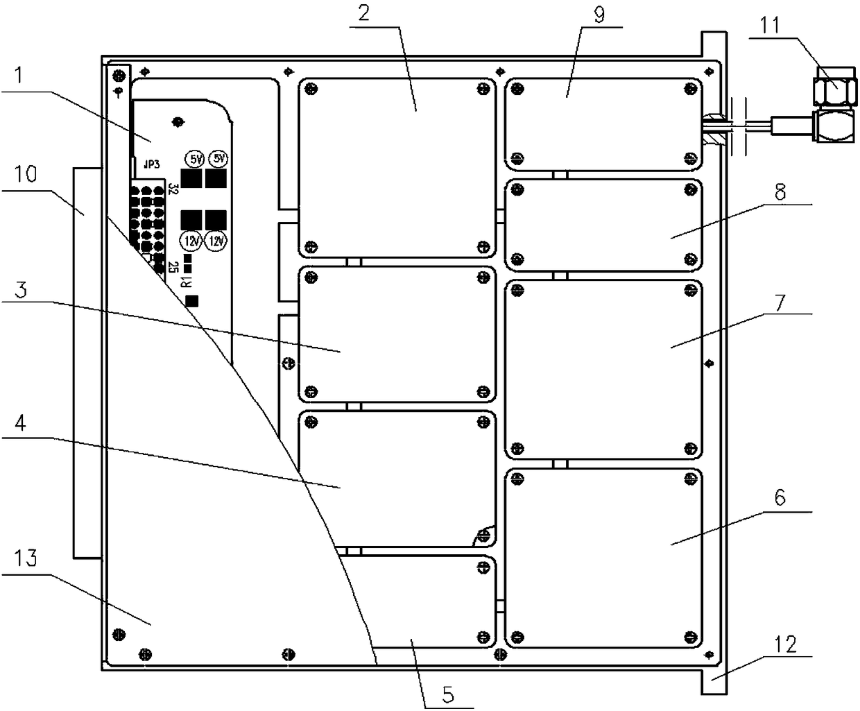
[0027] Such as figure 1 As shown, a frequency hopping frequency synthesizer includes a cavity 12; a channel unit is provided in the cavity 12, a cover plate 13 is provided on the cavity 12, and power supply and control are provided on both sides of the cavity 12 The signal interface 10 and the radio frequency signal output interface 11; the channel unit is respectively connected with the power supply and the control signal interface 10 and the radio frequency signal output interface 11; the channel unit is provided with an amplification module III 3, a DDS module 4, and a frequency division module 6, There is a band-pass filter inside the amplification module III3 (such as Figure 4 shown) and shaping circuits (such as Figure 5 shown), the band-pass filter and the shaping circuit can adopt any type in the prior art, the OUT end ...


PUM


Abstract

The invention provides a hopping frequency synthesizer comprising a cavity in which a channel unit is arranged, wherein a cover plate is arranged on the cavity, and a power supply and control signal interface and a radio frequency signal output interface are outwards arranged on two sides of the cavity; the channel unit is separately connected with the power supply and control signal interface andthe radio frequency signal output interface; an amplification module III, a DDS module and a frequency division module are arranged in the channel unit; a band-pass filter and an amplitude limiting circuit are arranged in the amplification module III; a DDS chip is arranged in the DDS module; and a frequency divider is arranged in the frequency dividing module. The hopping frequency synthesizer provided by the invention adopts a dual-layer shielding structure, each module is embedded into the cavity and covered with the small cover plate, and then covered with a big cover plate, and then dual-layer shielding is formed, so that the heat dissipation effect is improved while the electromagnetic shielding performance and isolation of each module are improved, and the heat dissipation problembetween the printed circuit boards of the modules is effectively solved.

Description

technical field [0001] The invention relates to a frequency hopping frequency synthesizer, which belongs to the technical field of wireless communication frequency hopping frequency. Background technique [0002] The frequency synthesizer is one of the key core component technologies in the frequency hopping communication system, but the frequency synthesizer involves a variety of frequencies and is prone to generate a variety of harmonics. Its frequency conversion time, frequency resolution, frequency range and output spurs directly affect The anti-interference performance of the fast frequency hopping communication system and the stability and reliability of the system, however, the locking time of the frequency synthesizer and other technical indicators are mutually restricted. [0003] In the prior art, a variety of methods are provided for the spurious suppression capability of the frequency synthesizer, such as a loop filter device for a fast broadband frequency hoppin...

Claims


Application Information

Patent Timeline
Patent Type & Authority Applications(China)
IPC IPC(8): H03L7/093H03L7/107
CPCH03L7/093H03L7/1075
Inventor 潘吉华魏旭窦立刚吴良金陈聪秀
Owner GUIZHOU AEROSPACE TIANMA ELECTRICAL TECH
Why Eureka
Try Eureka