UV primer paint spraying line

A paint spraying line and primer technology, applied in spray booths, spraying devices, pre-treated surfaces, etc., can solve the problems of blocked pipes, reduce work efficiency, waste, etc., and achieve the effects of easy reuse, wide application range, and improved quality

Pending Publication Date: 2018-09-11
临沂鼎宝机械科技有限公司
View PDF9 Cites 5 Cited by
  • Summary
  • Abstract
  • Description
  • Claims
  • Application Information

AI Technical Summary

Problems solved by technology

[0003] Need to use UV primer spraying line when using UV paint to spray furniture, and existing UV primer spraying line has the following problems in use: 1) because UV paint is ultraviolet photocuring paint, does not pass through ultraviolet photocuring Always maintain a liquid state, it is easy to hang when sprayed on the workpiece, and it is difficult to control the amount of diluent and curing agent added. If the concentration of UV paint is too high, it is easy to block the nozzle, resulting in the failure of spraying of UV paint, resulting in the failure of the painting line. Normal work; 2) When spraying UV paint on the workpiece, the workpiece is usually placed in a closed box. Since the UV paint mist will spread to every corner of the box during painting, the UV paint mist will form after gathering. After a certain volume, it will drip down, and it will affect the spraying effect after dripping on the workpiece. The width of the workpiece is different. Necessary waste; 3) Due to the different heights of the workpieces, the height of the spray gun of the existing UV primer spraying line cannot be adjusted, and the effect of spraying cannot be guaranteed, so secondary spraying is required, which reduces work efficiency; 4) UV paint passes through the pipeline The spray gun sprays the workpiece. After the spraying work is completed, there is still UV paint in the pipeline. If the UV paint in the pipeline does not flow for a long time, it will solidify in the pipeline and block the pipeline, causing the UV paint to fail to flow normally during the next spraying. Normal operation of the spraying device

Method used


Image

  • UV primer paint spraying line
  • UV primer paint spraying line
  • UV primer paint spraying line

Examples


Embodiment 1

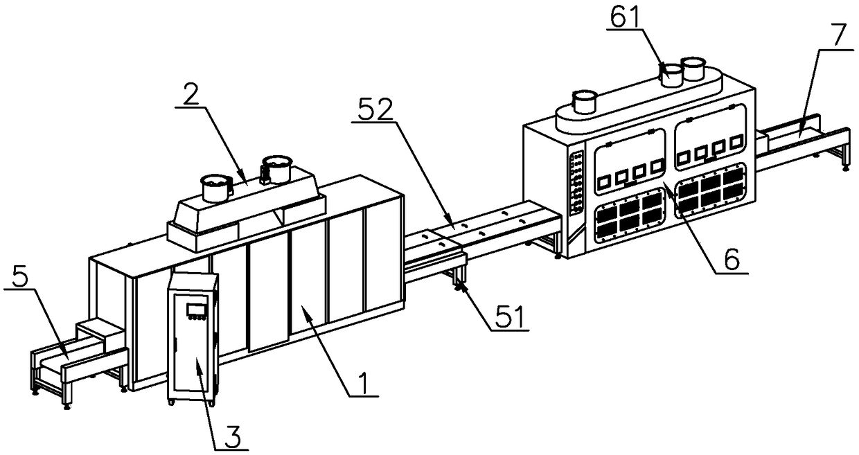
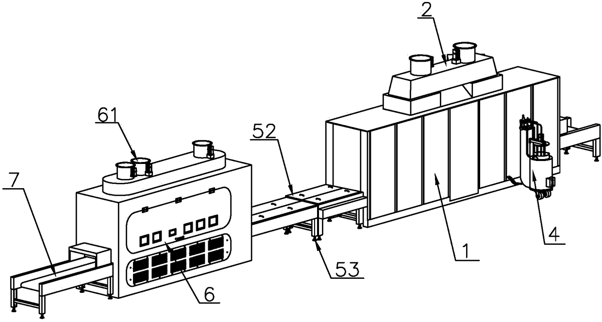
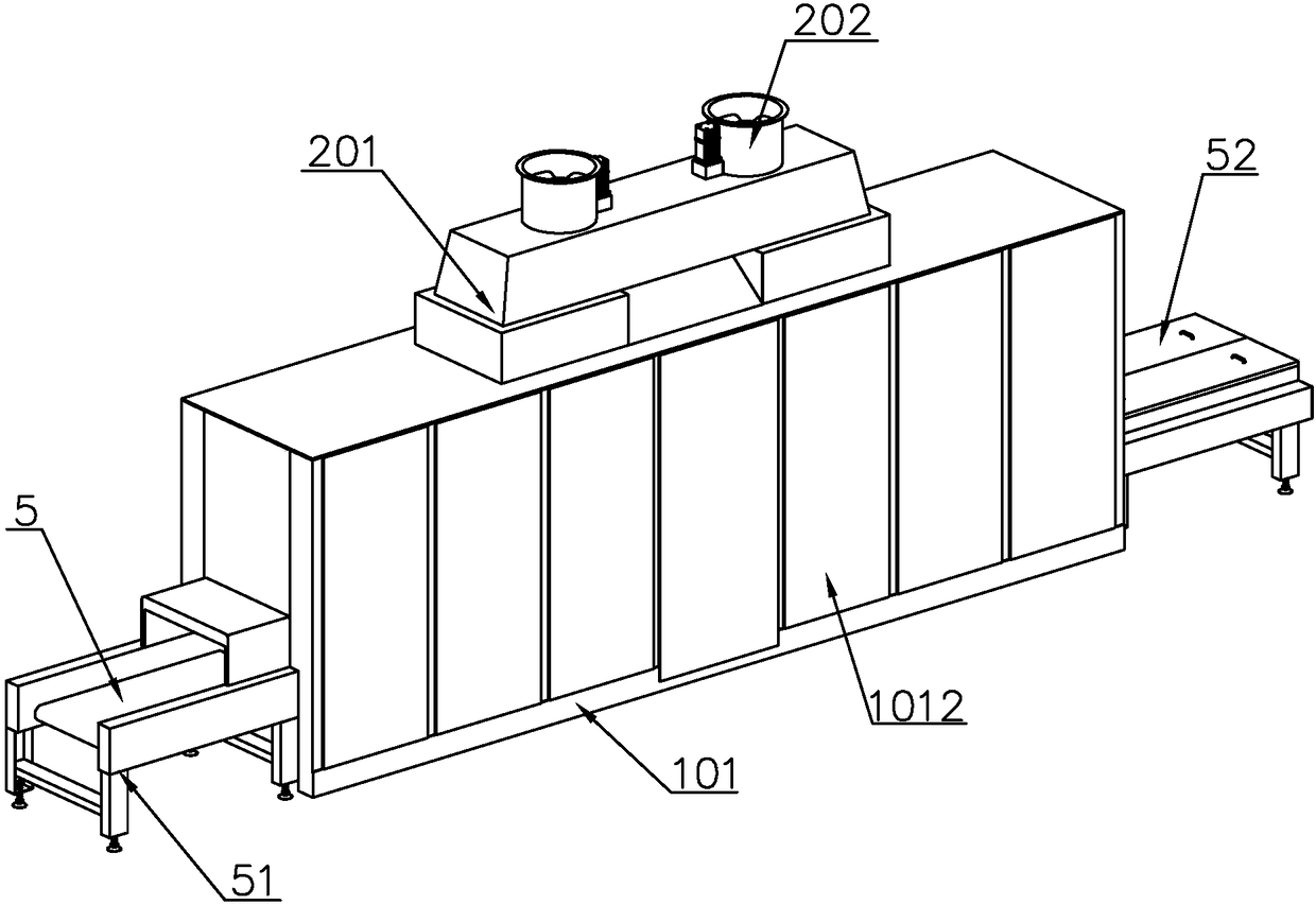
[0047] Such as Figure 1-13 As shown, a UV primer painting line includes a painting device 1, a negative pressure device 2, a control cabinet 3, a conveyor belt I5, a drying device 6, and a conveyor belt II7. There is a control cabinet 3 on one side of the device 2, and a lifting mechanism 8 and a gun bag 9 are arranged inside the painting device 1. The lifting mechanism 8 drives the gun bag 9 to adjust the height, and the workpiece is sprayed with UV paint through the gun bag 9. The painting device 1 is two There is a conveyor belt I5 at the end, and a drying device 6 is installed on one side of the conveyor belt I5, and a conveyor belt II7 is arranged in the drying device 6, and the conveyor belt II7 extends to both sides of the drying device 6, and the workpiece is transported by the conveyor belt I5 to the paint spraying device 1. For the spraying of UV paint, the scattered paint mist is discharged through the negative pressure device. After the spraying is completed, the ...

Embodiment 2

[0056] Such as Figure 7 As shown, the difference from Embodiment 1 is that a connecting plate 810 is provided below the gun bag 9, and a wind direction guide plate 811 is provided on the inside of the connecting plate 810. One end of the wind direction guide plate 811 is installed on the connecting plate 810 through a pin shaft, and the wind direction guides The other end of the plate 811 is overlapped in the groove at the bottom of the baffle plate 102. When the gun bag 9 moves up and down, the gun bag 9 drives the wind direction guide plate 811 to move through the connecting plate 810 to adjust the angle of the wind direction guide plate 811. The angle of the plate 811, and then adjust the wind direction, to ensure that the paint mist will not stay too much at the spray gun I903 and pollute the spray gun I903.

Embodiment 3

[0058] Such as Figure 14 As shown, different from Embodiment 1, the bottom of the gun bag 9 is provided with a scraping mechanism, and the scraping mechanism includes a brush plate 905, a motor II 906, a steel belt machine I 907, a photoelectric sensor II 908, and the motor II 906 is set At one end of the placement frame 901, a steel belt machine I907 is arranged on one side of the motor II906, and the steel belt machine I907 is set inside the bottom of the placement frame 901. A brush plate 905 is provided on the steel belt machine I907, and a photoelectric sensor is installed at the other end of the placement frame 901. Ⅱ908, after the spraying of the workpiece by the gun package 9, the motor Ⅱ906 drives the steel belt machine Ⅰ907 to make the brush plate 905 scrape the spray gun Ⅰ903 and the gun frame Ⅰ902 to prevent UV paint droplets remaining on the spray gun Ⅰ903 and the gun frame Ⅰ902 onto the workpiece.


PUM


Abstract

The invention discloses a UV primer paint spraying line. The UV primer paint spraying line comprises a paint spraying device, a paint mist separating device, a control cabinet, a conveyor belt I, a drying device and a conveyor belt II, wherein the paint mist separating device is arranged in the paint spraying device; the control cabinet is arranged at one side of the paint spraying device; the twoends of the paint spraying device are equipped with the conveyor belt I; the drying device is arranged at one side of the conveyor belt I; the conveyor belt II is arranged in the drying device; and the conveyor belt II extends to the two sides of the drying device. The UV primer paint spraying device is used for heating UV paint to reduce viscosity of the UV paint, and avoids generation of a phenomenon that UV paint blocks a spray head or sags on a workpiece; according to the width of the workpiece, a solenoid valve can control working quantity of spray guns during spraying, and reduces unnecessary waste of UV paint; UV paint gas spray gathered inside a box body is not in contact with the workpiece under action of a shutter and a negative-pressure device, so that the spraying effect is guaranteed; and UV paint in a pipeline flows back into a UV paint barrel while not used, so that smoothness in the pipeline is guaranteed.

Description

technical field [0001] The invention belongs to the technical field of painting, in particular to a UV primer painting line. Background technique [0002] UV paint is currently the most widely used furniture paint. Its main features are: after strong ultraviolet light curing treatment, the color is stable, and it will last forever. It can effectively solve the problem of fading and color difference of the door panel. Orange peel is one of the more environmentally friendly and healthy paint door panels in the world. The hardness of the door panel is twice that of other paint door panels. It is resistant to scratches, acid and alkali, and is not easy to deform; [0003] Need to use UV primer spraying line when using UV paint to spray furniture, and existing UV primer spraying line has the following problems in use: 1) because UV paint is ultraviolet photocuring paint, does not pass through ultraviolet photocuring Always maintain a liquid state, it is easy to hang when sprayed...

Claims


Application Information

Patent Timeline
Patent Type & Authority Applications(China)
IPC IPC(8): B05B16/20B05B13/02B05B15/68B05B14/43B05B14/40B05D3/06B05B12/10B05B13/04B05B15/50B05B16/40
CPCB05B12/10B05B13/0221B05B13/0278B05B13/041B05B14/40B05B14/43B05B15/50B05B15/68B05B16/20B05B16/40B05B16/95B05D3/067
Inventor 吴浩田
Owner 临沂鼎宝机械科技有限公司
Why Eureka
Try Eureka