Worrkpiece polishing device

A workpiece and worktable technology, applied in the field of grinding equipment, can solve the problems of multi-processing cost and increase of clamping power mechanism, and achieve the effect of fast and convenient clamping and fixing of parts, stable adsorption effect, and energy saving effect

Inactive Publication Date: 2018-09-11
宁波鑫神泽汽车零部件有限公司
View PDF6 Cites 6 Cited by
  • Summary
  • Abstract
  • Description
  • Claims
  • Application Information

AI Technical Summary

Problems solved by technology

[0006] The purpose of the present invention is to provide a workpiece grinding device to solve the

Method used


Image

  • Worrkpiece polishing device
  • Worrkpiece polishing device
  • Worrkpiece polishing device

Examples


Embodiment Construction

[0024] The present invention will be described in further detail below by means of specific embodiments:

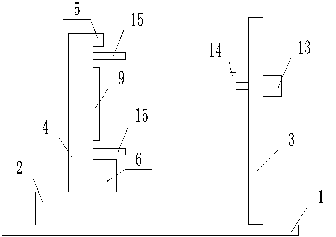
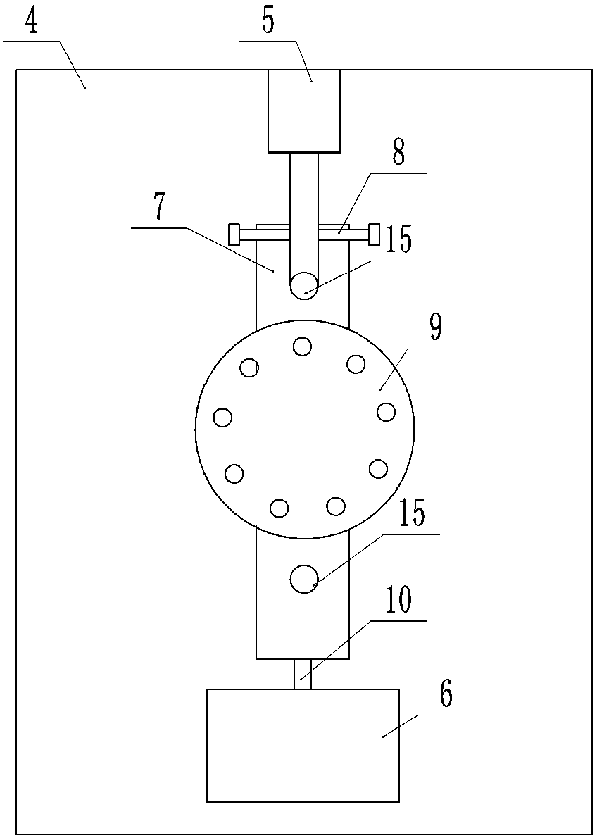
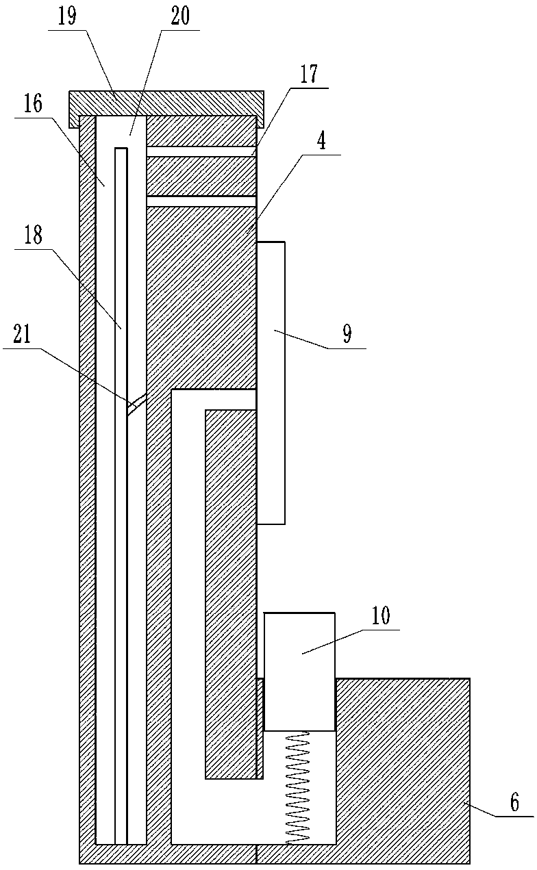
[0025] The reference signs in the drawings of the description include: frame 1, workbench 2, support plate 3, fixed plate 4, cylinder 5, fixed block 6, rack 7, first gear 8, suction cup 9, slide bar 10, convex Teeth 11, servo motor 13, grinding disc 14, cross bar 15, cavity structure 16, collection hole 17, electrostatic plate 18, upper cover 19, opening 20, scraper 21.

[0026] Such as figure 1 with image 3 As shown, a workpiece grinding device includes a frame 1, a workbench 2 is welded on the left part of the frame 1, a vertical fixing plate 4 is welded on the upper part of the workbench 2, and a cavity structure 16 is opened in the fixing plate 4 , the bottom of the cavity structure 16 is equipped with an electrostatic plate 18, and the electrostatic plate 18 is connected with an electrostatic line; the upper part of the fixed plate 4 is equipped with a cylinder 5,...


PUM


Abstract

The invention belongs to the technical field of polishing equipment, and particularly discloses a worrkpiece polishing device. The worrkpiece polishing device comprises a machine frame. A workbench and a supporting plate are arranged on the machine frame, a fixing plate and a suction disc are arranged on the workbench, an air cylinder, a fixing block and a guide rail are arranged on the fixing plate, and a transverse rod is arranged on a piston rod of the air cylinder. A ratchet and pawl structure is arranged on the piston rod, and a ratchet in the ratchet and pawl structure meshes with a rack. A sliding hole is formed in the fixing block, a sliding rod is arranged in the sliding hole and connected with the rack, and hole channels are connected between the sliding hole and through holes. Aservo motor is arranged on a track, a polishing disc and a second gear are arranged on an output shaft of the servo motor, and the second gear meshes with convex teeth. Switches which control the servo motor to backwards rotate are arranged at the two ends of the track. The worrkpiece polishing device is mainly used for polishing parts, and solves the problem that due to the fact that a pluralityof clamping power mechanisms are arranged when parts are polished, the processing cost is increased.

Description

technical field [0001] The invention belongs to the technical field of grinding equipment, and specifically discloses a workpiece grinding device. Background technique [0002] Mechanical parts are usually made by cutting, cutting, drilling, stamping, etc. The parts made by these processing methods have the required mechanical properties, and the made parts provide convenience for the assembly and maintenance of mechanical equipment. [0003] After the mechanical parts are processed and formed, there are usually burrs. If the burrs are not removed, it will bring inconvenience to the subsequent use of the parts; when dealing with the surface of disc-shaped and ring-shaped workpieces, it is first necessary to make different fixtures to clamp the workpiece Hold it, and the cost is high; in addition, the hand-held grinder moves back and forth along the workpiece to grind the surface of the workpiece. Since the hand needs to hold the grinder for a long time, the hand will be sore...

Claims


Application Information

Patent Timeline
IPC IPC(8): B24B41/02B24B41/06B24B55/06
CPCB24B41/02B24B41/06B24B55/06
Inventor 王健
Owner 宁波鑫神泽汽车零部件有限公司
Why Eureka
Try Eureka