
Plane optical element sub surface damage detecting method

A technology for subsurface damage and optical components, which is applied in the field of ultra-precision processing and inspection, and can solve problems such as damage to optical components, unintuitive measurement results, and poor practicability of subsurface damage detection.

Inactive Publication Date: 2018-09-11
HUNAN INST OF TECH
View PDF5 Cites 9 Cited by
  • Summary
  • Abstract
  • Description
  • Claims
  • Application Information

AI Technical Summary

Problems solved by technology

Destructive inspection can lead to damage or failure of expensive optical components, and the inspection process is highly dependent on operator experience
Non-destructive testing methods have problems such as low measurement accuracy, shallow detection depth, unintuitive measurement results, and high cost of testing systems.
The establishment of the prediction model in the theoretical prediction method is basically based on empirical formulas, and the introduction of some assumptions makes it difficult to guarantee the accuracy of the prediction results
In addition, the application of the destructive detection methods, non-destructive detection methods and theoretical prediction methods listed above basically stays in the processing samples in the laboratory environment as the detection object, and is aimed at large and medium-sized planar optics in the background of engineering applications. Less practical for subsurface damage detection of components

Method used


Image

  • Plane optical element sub surface damage detecting method
  • Plane optical element sub surface damage detecting method
  • Plane optical element sub surface damage detecting method

Examples


Embodiment Construction

[0036] In order to facilitate the understanding of those skilled in the art, the present invention will be further described below in conjunction with specific embodiments and drawings.

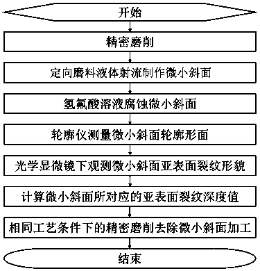
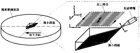
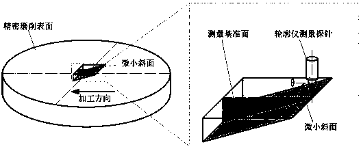
[0037] The technical concept of the present invention is based on the following solutions, such as figure 1 Shown: The directional abrasive liquid jet is used to make the tiny bevel shown in the figure on the surface of the plane optical element that has been finely ground (that is, the aforementioned observation bevel), and then the hydrofluoric acid solution is used to corrode the tiny bevel to fully expose the edge of the optical element. The sub-surface crack layer in the direction of the inclined plane is then used to measure the contour curve of the small inclined plane with the scanning function of the profiler, and the distribution of the sub-surface cracks along the direction of the small inclined plane is obtained with the help of the micro-motion platform and clear imaging function of t...


PUM


Abstract

The invention discloses a plane optical element sub surface damage detecting method. The plane optical element sub surface damage detecting method comprises the steps that firstly, directional abrasive material liquid is adopted to be subject to jet flow to the surface of a plane optical element to make an observation slope, and the depth, penetrating into the plane optical element, of the observation slope should meet the requirement that the sub surface crack can be sufficiently exposed; secondly, a hydrofluoric acid solution is used for etching the observation slope, and the plane optical element is sufficiently exposed along the sub surface crack layer in the observation slope direction to be conveniently observed; thirdly, with the aid of the scanning function of a contourgraph, the profile curve of the observation slope is measured, and the included angle value between the horizontal plane and the observation slope can be obtained; fourthly, with aid of a micro motion stage and the clear imaging function of an ultra-field-depth optical microscope, the sub surface crack distribution condition in the observation slope direction can be obtained, and the moving total distance ofthe micro motion stage when the final crack disappears can be determined; fifthly, in combination with the moving total distance of the micro motion stage when the final crack disappears and the included angle value between the horizontal plane and the observation slope in the third step, the sub surface crack depth value can be calculated.

Description

Technical field [0001] The invention relates to the technical field of ultra-precision processing and detection, in particular to a method for detecting subsurface damage of a planar optical element. Background technique [0002] Plane optical components (such as plane mirrors, plane standard mirrors) are an important part of the optical system. In the optical system of the National Ignition Facility (NIF), 192 beams require a total of about 7,500 large and medium-sized optical components with a size of 420mm×420mm or more, plus backup optical components and small-aperture optical components. About 30,000 optical components. They are characterized by high-precision surface shapes, ultra-smooth surfaces, high surface / subsurface quality and large-volume requirements. It is worth noting that about 80% of the optical components in the National Ignition Device NIF are planar components (including polarizers, neodymium glass plates, mirrors, and pulse compression gratings, etc.). Onl...

Claims


Application Information

Patent Timeline
IPC IPC(8): B24B49/12B24B13/00G01B11/22G01B21/18C03C15/00B24C1/04
CPCB24B49/12B24B13/00B24C1/04C03C15/00G01B11/22G01B21/18
Inventor 李平金滩刘安民陈思羽吴远志
Owner HUNAN INST OF TECH
Learn More