Plate cutting device

A cutting device and plate technology, applied in the field of plate processing, can solve the problems of increasing plastic plate processing procedures, reducing production efficiency, and low processing accuracy, and achieve the effects of improving cutting chamfering efficiency, improving chamfering accuracy, and improving stability

Inactive Publication Date: 2018-09-11
宁波得晴电器科技有限公司
View PDF4 Cites 0 Cited by
  • Summary
  • Abstract
  • Description
  • Claims
  • Application Information

AI Technical Summary

Problems solved by technology

[0003] Therefore, in the cutting of plastic boards, the section of the plastic board is generally trimmed manually. The trimming rate of the cross-section is inconsistent during manual operation, the processing accuracy is low, not flexible enough, and the production efficiency is also reduced; and in the plastic board cutting process It is easy to generate splashes of plastic debris, pollute the environment, and lead to a large waste of plastic materials
Sometimes after cutting the plastic board, there is also the work of rounding the cross-section of the plastic board. Generally, the cutting and chamfering of the plastic board are separated, but this will increase the processing of the plastic board. At the same time, it is necessary to fix the same plastic plate multiple times, and the operation is complicated

Method used


Image

  • Plate cutting device
  • Plate cutting device
  • Plate cutting device

Examples


Embodiment Construction

[0020] Further detailed explanation through specific implementation mode below:

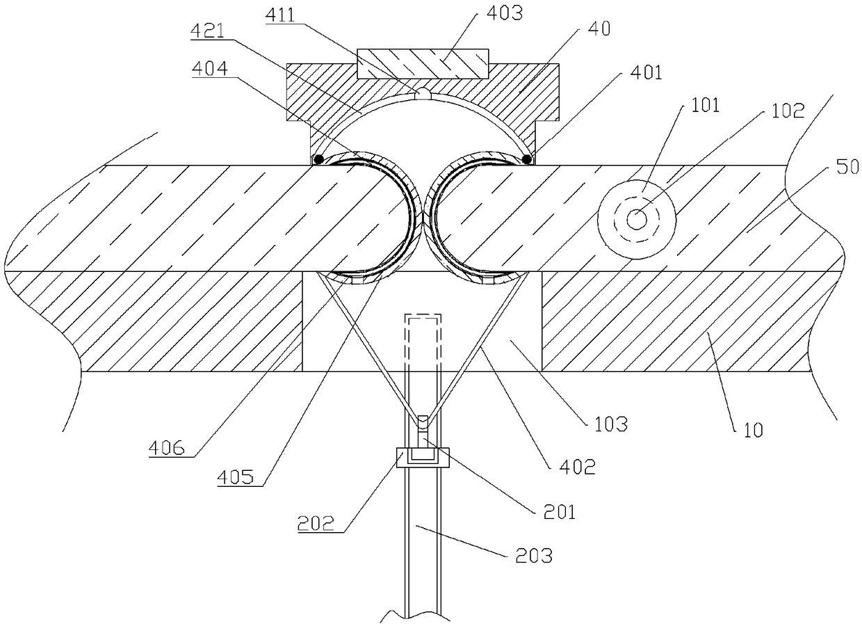
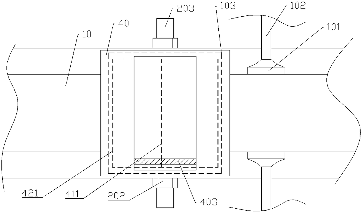
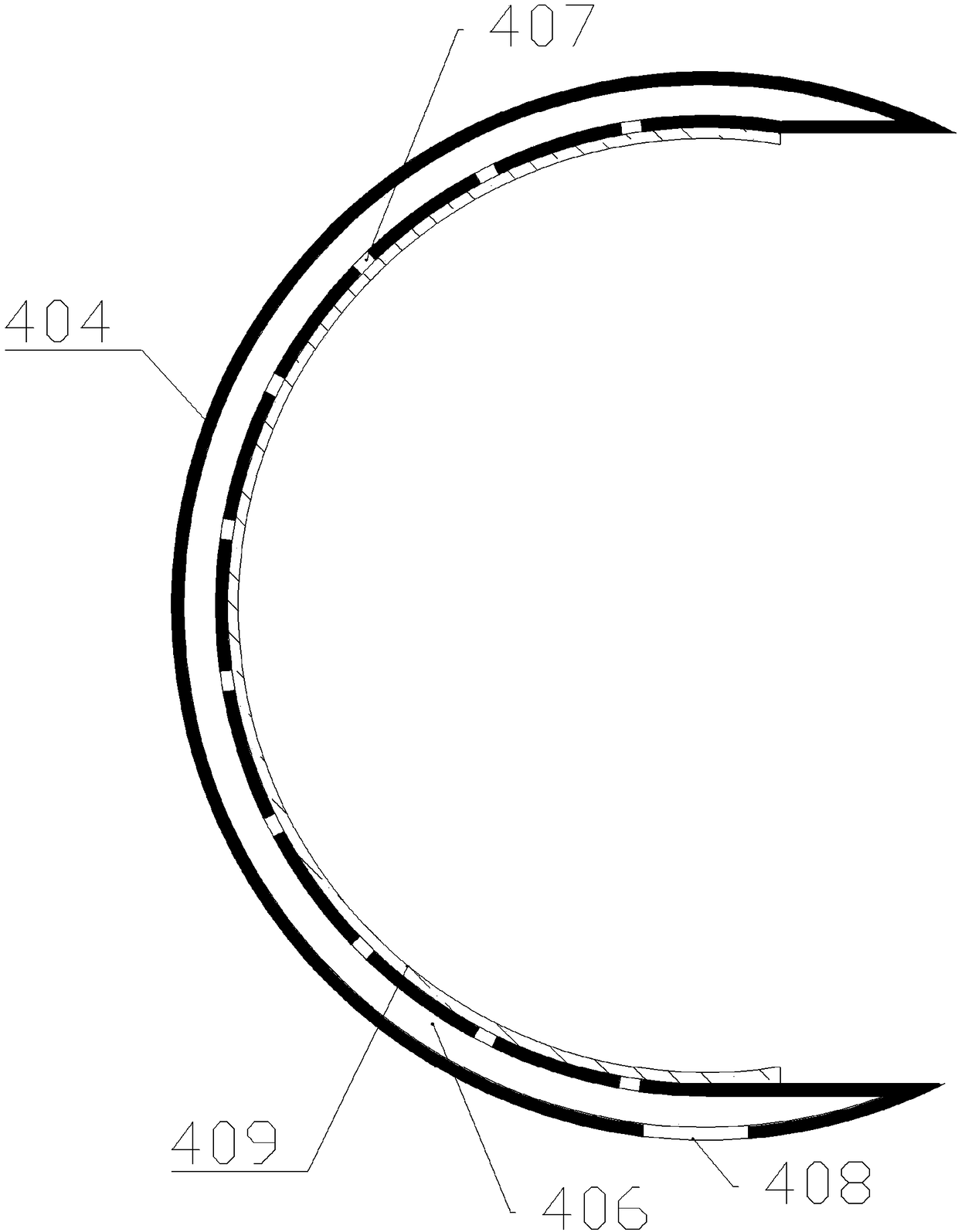
[0021] The reference signs in the accompanying drawings include: conveyor belt 10, suction cup 101, support rod 102, cutting through groove 103, hook 201, first slide rail 202, second slide rail 203, fixed block 40, slide groove 411, sliding surface 421, slider 401, pull cord 402, magnet 403, elastic cutter 404, heating wire 405, cavity 406, collection hole 407, discharge hole 408, friction bar 409, plastic plate 50.

[0022] The embodiment is basically as attached figure 1 , attached figure 2 And attached image 3 Shown: a plate cutting device, including a cutting mechanism, several suction cups 101, several support rods 102, a moving mechanism and a conveyor belt 10 for conveying plastic plates 50, the conveyor belt 10 is horizontally arranged, and the conveyor belt 10 is provided with several cutting through grooves 103, support rods 102 are welded horizontally on both sides of the conveyo...


PUM


Abstract

The invention relates to the field of plate processing, and particularly discloses a plate cutting device. The plate cutting device comprises a cutting mechanism and a moving mechanism. The cutting mechanism comprises a fixed block and two cutting units. Each cutting unit comprises a sliding block, a stay cord, a circular-arc-shaped elastic cutting knife and an electric heat wire, and the outer circles of the elastic cutting knives are wrapped with the electric heat wires. The fixed block is welded to on the upper portion of a conveying belt. The lower surface of the fixed block is provided with a sliding surface for allowing the sliding blocks to slide. A sliding groove is formed in the central line of the sliding surface. The bending directions of the elastic cutting knives in the two cutting units are opposite. The two elastic cutting knives are vertically arranged. The upper ends of the elastic cutting knives and the sliding blocks are welded. The lower ends of the sliding blocks and one ends of the stay cords rare welded. The inner circles of the elastic cutting knives are provided with friction strips. Knife edges of the elastic cutting knives are located on the two sides ofthe elastic cutting knives. According to the scheme, a plastic plate can be cut and subjected to chamfering simultaneously, the processing work procedure of the plastic plate is reduced, and the processing efficiency of the plastic plate is improved.

Description

technical field [0001] The invention belongs to the field of plate processing, and in particular relates to a plate cutting device. Background technique [0002] Plastic sheet is a commonly used manufacturing material in household electrical appliances. In the conventional processing of plastics, it is often necessary to cut the sheet-shaped plastic. Because plastic products have a certain hardness, when cutting, the cutting section of the plastic sheet will be There are many scratches or burrs. [0003] Therefore, in the cutting of plastic boards, the section of the plastic board is generally trimmed manually. The trimming rate of the cross-section is inconsistent during manual operation, the processing accuracy is low, not flexible enough, and the production efficiency is also reduced; and in the plastic board cutting process It is easy to generate splashes of plastic debris, pollute the environment, and lead to a large waste of plastic materials. Sometimes after cutting...

Claims


Application Information

Patent Timeline
IPC IPC(8): B26D1/04B26D7/27
CPCB26D1/04B26D7/27
Inventor 许根海
Owner 宁波得晴电器科技有限公司
Why Eureka
Try Eureka