Vacuum infusion process

A vacuum infusion and process technology, applied in household appliances, other household appliances, household components, etc., can solve problems such as difficulty in film formation, low work efficiency, cuts, etc., to improve vacuum infusion efficiency, increase soaking speed, and save consumption Effect

Active Publication Date: 2020-11-10
JIANGSU GOLDWIND SCI & TECH CO LTD
View PDF2 Cites 0 Cited by
  • Summary
  • Abstract
  • Description
  • Claims
  • Application Information

AI Technical Summary

Problems solved by technology

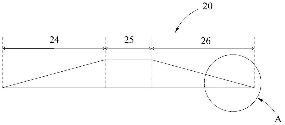
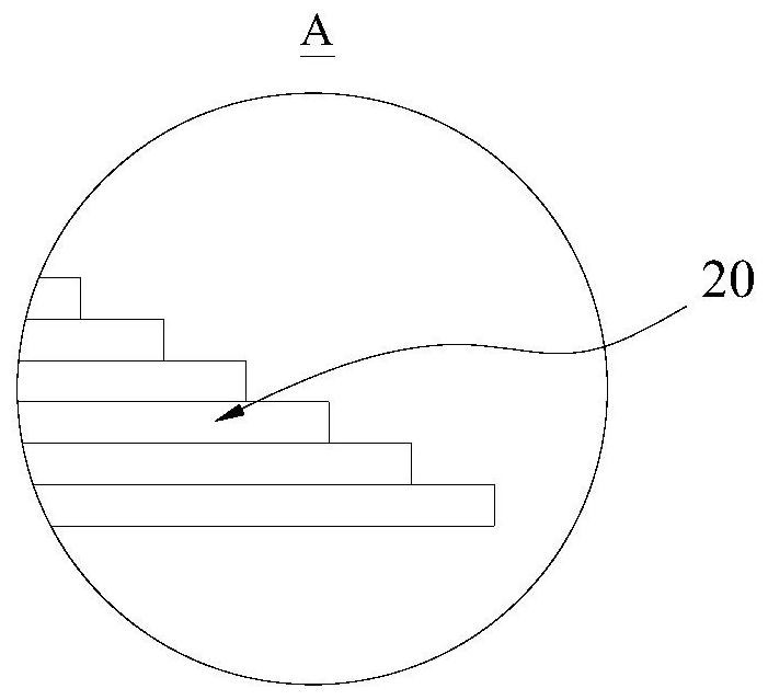
[0004] However, in the actual pouring process, there is an obvious problem of pouring and penetration. Taking the main beam of the pouring blade as an example, the glass fiber cloth or carbon fiber cloth at both ends starts from one layer, and the closer to the middle, the glass fiber or carbon fiber cloth. The more cloth layers, the practical problem is that during the pouring process of the entire blade main beam, the two ends are poured first, and the thicker the middle layer is, the slower the pouring is, that is, the longer it takes. Therefore, there will still be resin poured into the place where the end of the main beam of the blade has been filled. Although the flow rate has decreased, it will still cause resin-rich phenomenon at both ends.
[0005] In addition, in the current vacuum infusion process, there is usually a large amount of resin remaining in the ohmic tube, which causes serious material waste in the blade manufacturing process, and when the perfusion resin remains in the ohmic tube, due to the high strength of the solidified FRP, resulting in Structural parts such as the main beam of the blade are difficult to film, which is easy to cause physical injury such as cuts, and also causes waste of ohmic tube materials
[0006] In addition, when the perfusion resin remains in the ohmic tube, the perfusion resin will generate heat during the curing process, causing the local temperature to be too high. Partial whitening quality problem
In order to avoid the above problems, it is usually necessary to manually check and confirm continuously, the work efficiency is low, and the vacuum mold bag laid may be damaged.

Method used


Image

  • Vacuum infusion process
  • Vacuum infusion process
  • Vacuum infusion process

Examples


Embodiment Construction

[0035]Features and exemplary embodiments of various aspects of the invention will be described in detail below. In the following detailed description, numerous specific details are set forth in order to provide a thorough understanding of the present invention. It will be apparent, however, to one skilled in the art that the present invention may be practiced without some of these specific details. The following description of the embodiments is only to provide a better understanding of the present invention by showing examples of the present invention. In the drawings and the following description, at least some well-known structures and techniques have not been shown in order to avoid unnecessarily obscuring the present invention; and, for clarity, the dimensions of some structures may have been exaggerated. The same reference numerals in the drawings denote the same or similar structures, and thus their detailed descriptions will be omitted. Furthermore, the features, str...


PUM

PropertyMeasurementUnit
lengthaaaaaaaaaa

Abstract

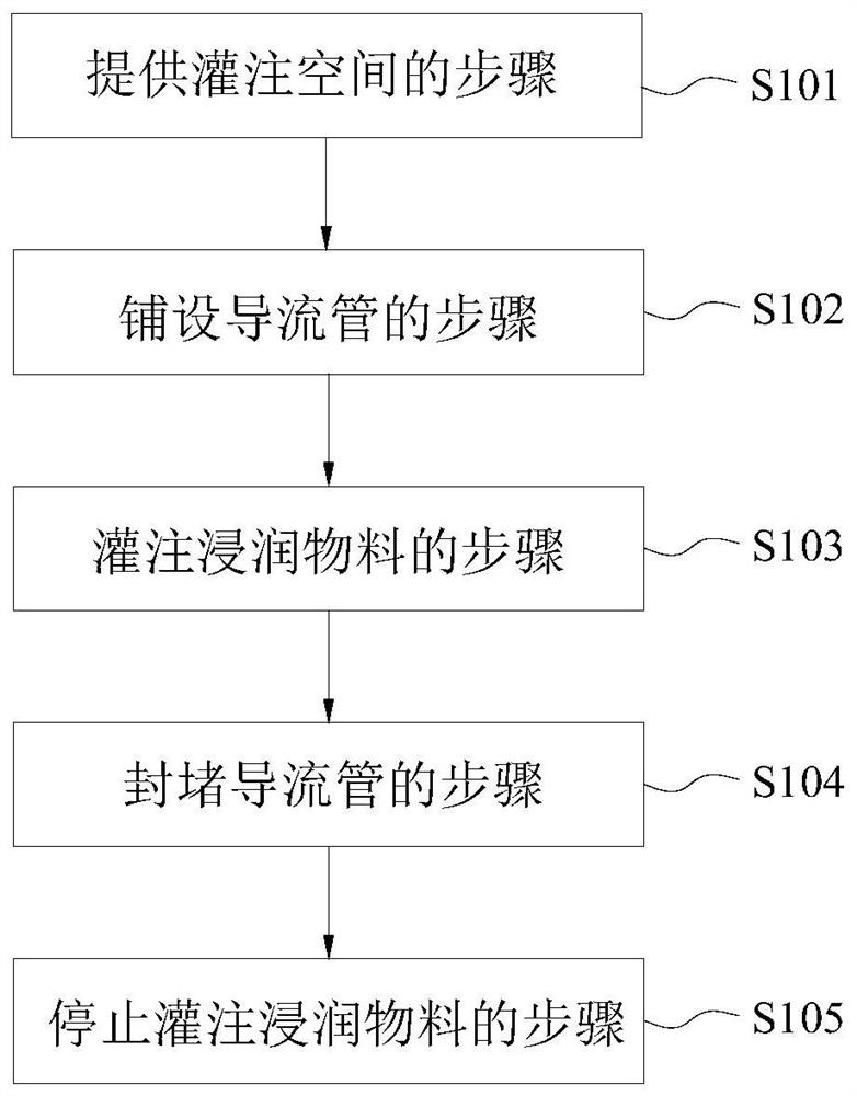
The invention provides a vacuum perfusion technology. The vacuum perfusion technology comprises the following steps: providing a perfusion space; paving a reinforcing material on the perfusion space;paving a flow guide pipe, wherein the flow guide pipe is provided with a perfusion opening, a first flow channel, a second flow channel and a filling opening, the first flow channel is communicated with a first region and the second flow channel is communicated with a second region; perfusing a wetting material; enabling the wetting material to enter the corresponding first region and second region from the first flow channel and the second flow channel respectively; blocking the flow guide pipe; when the reinforcing material reaches a first pre-set wetting degree, filling the flow guide pipewith a filling material through the filling opening, so as to enable the filling material to gradually block the first flow channel, reduce the flowing of the wetting material in the flow guide pipe toward the first region, and increase the flowing the wetting material toward the second region through the second flow channel. By adopting the vacuum perfusion technology, a condition that excessivewetting materials are retained in the flow guide pipe can be avoided and one or more aims of improving the vacuum perfusion efficiency and reducing the vacuum perfusion cost can be realized.

Description

technical field [0001] The invention relates to the technical field of infusion process molding, in particular to a vacuum infusion process. Background technique [0002] Due to the advantages of high specific strength and specific modulus, excellent designability and good fatigue resistance, advanced composite materials have been widely used in aerospace, fan blades, transportation, construction, electromechanical industry and other fields. At present, composite materials made by vacuum-assisted infusion molding technology have gradually become a new type of material for the preparation of large-scale, large-thickness and complex components, especially in the fields of ships and wind power. [0003] For example, in the field of wind power, at present, most blades, especially large blades, mainly adopt a multi-step molding method (two or more composite material molding methods), that is, the upper and lower shells and shear webs of the blades are first prepared respectively....

Claims


Application Information

Patent Timeline
Patent Type & Authority Patents(China)
IPC IPC(8): B29C70/36B29C70/54B29L31/08
CPCB29C70/36B29C70/54B29L2031/082
Inventor 马小军李小明樊祥希
Owner JIANGSU GOLDWIND SCI & TECH CO LTD
Why Eureka
Try Eureka